Motor rotor

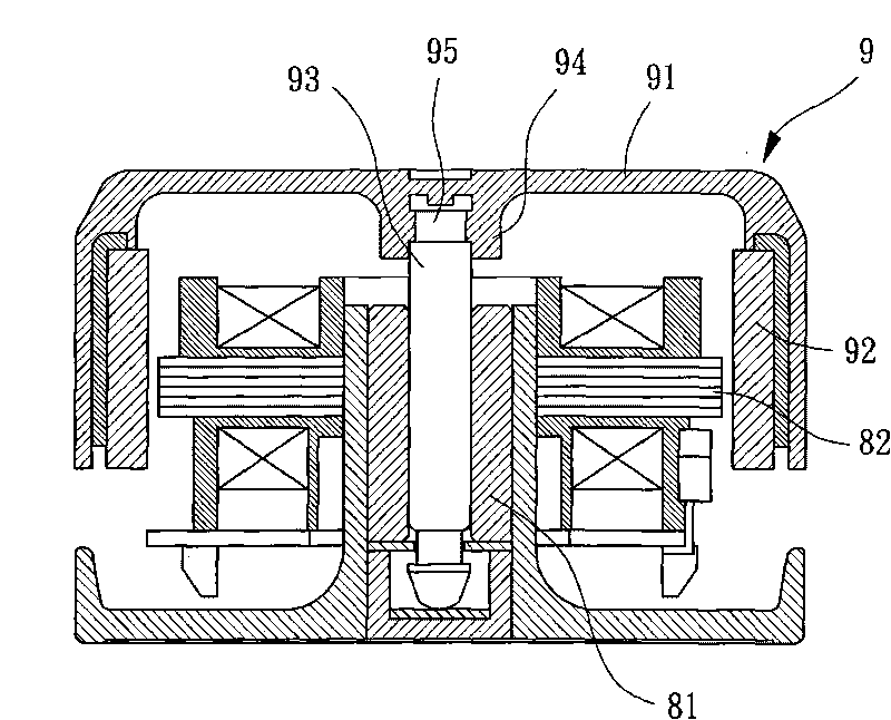
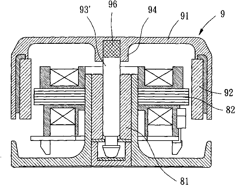
A technology for motor rotors and joints, which is applied in the direction of magnetic circuit rotating parts, mechanical energy control, electric components, etc., and can solve problems such as the limited area of ​​the hub 91, the limited design space for miniaturization or thinning of the motor, and the reduction of the joint area.

Active Publication Date: 2010-06-23
SUNONWEALTH ELECTRIC MACHINE IND
View PDF0 Cites 2 Cited by
  • Summary
  • Abstract
  • Description
  • Claims
  • Application Information

AI Technical Summary

Problems solved by technology

However, under the condition that the overall height of the motor is limited, the length of the mandrel 93, 93' is fixed, so when the hub 91 is provided with a shaft seat 94 or has a larger wall thickness for covering the mandrel 93 , 93', the distance for the mandrel 93, 93' to be threaded on the bearing 81 will be reduced, making the motor rotor 9 prone to rotation deflection, but if the mandrel 93, 93' is threaded longer When the distance from the bearing 81 is greater than that, the area where the hub 91 can cover the mandrel 93, 93' is limited
[0005] Therefore, when reducing the height of the shaft seat 94 of the existing structure hub 91, the bonding area between the wheel hub 91 and the mandrel 93 will be reduced, and the bonding strength will be reduced, but if the height of the shaft seat 94 of the wheel hub 91 is not reduced, the It also relatively limits the overall miniaturization or thinning design space of the motor
Therefore, the above-mentioned existing structures are not suitable for miniaturization or thinning motors

Method used


Image

  • Motor rotor
  • Motor rotor
  • Motor rotor

Examples


Embodiment Construction

[0034] In order to make the above-mentioned and other objects, features and advantages of the present invention more comprehensible, the preferred embodiments of the present invention are specifically cited below, together with the accompanying drawings, as follows:

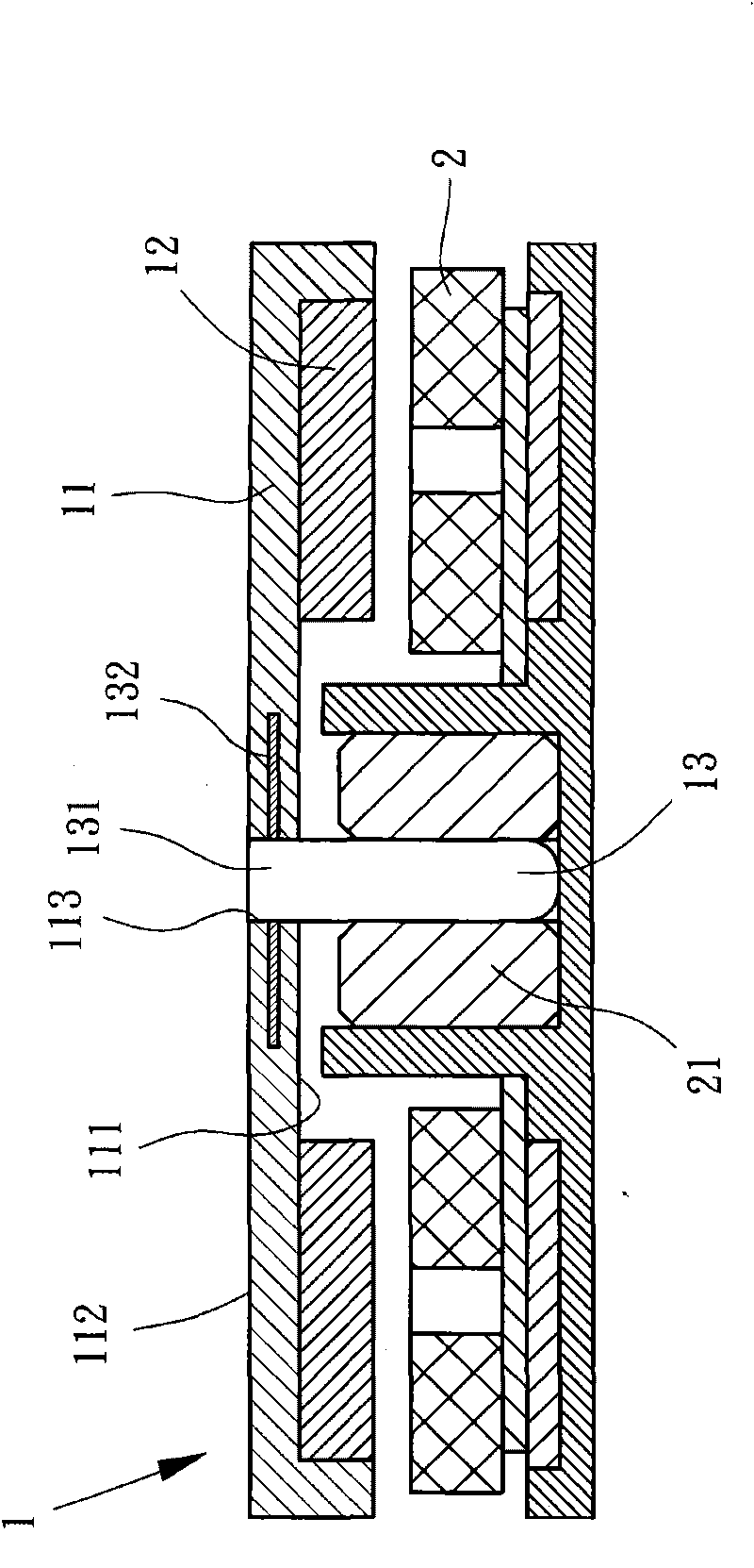
[0035] Please refer to image 3 As shown, the rotor 1 of the first embodiment of the present invention includes a hub 11 , a permanent magnet 12 and a spindle 13 .

[0036] Two opposite sides of the hub 11 are respectively an inner surface 111 and an outer surface 112 , and an assembly hole 113 is defined in the center of the hub 11 . Wherein, the assembling hole 113 may be selected as a blind hole (not shown), or may be selected as a through hole penetrating from the inner surface 111 to the outer surface 112 of the hub 11 (as shown in this embodiment).

[0037] The permanent magnet 12 is disposed on the inner surface 111 of the hub 11 , and is preferably disposed around the outer periphery of the assembly hole...


PUM


Abstract

The invention relates to a motor rotor which comprises a hub, a permanent magnet and a mandrel; wherein the hub is provided with an inner surface and an outer surface; an assembly hole is formed at the center of the inner surface of the hub; the permanent magnet is arranged on the inner surface of the hub in an encircling manner; the mandrel is provided with two ends, one end is a binding end, and the binding end is fixed in the assembly hole of the hub and is provided with a binding piece; the binding piece radially extends to the peripheral surface of the mandrel and is embedded in the hub. Therefore, the binding piece can radially extend and the binding area between the hub and the mandrel is increased, so that the excellent binding strength is provided, and simultaneously, the whole motor has miniaturized or thin design space.

Description

technical field [0001] The invention relates to a motor rotor, in particular to a motor rotor applied to a small motor. Background technique [0002] refer to figure 1 As shown, the existing motor rotor 9 includes a hub 91 , a permanent magnet 92 and a spindle 93 . The center of the inner side of the hub 91 has a shaft seat 94, the permanent magnet 92 is arranged around the inner peripheral surface of the hub 91, the mandrel 93 has two ends, and one end is a coupling end, and the coupling end is fixedly combined with the hub 91 central shaft seats 94. Thereby, when the spindle 93 of the rotor 9 is rotatably disposed in the center of the bearing 81 of the motor, the rotor 9 can be driven to rotate by means of a stator 82 . [0003] Refer again figure 1 and 2 As shown, in general, the fixed connection between the joint ends of the mandrels 93, 93' of the existing structure and the shaft seat 94 of the hub 91 can be divided into two types, one of which is on the outer peri...

Claims


Application Information

Patent Timeline
Patent Type & Authority Applications(China)
IPC IPC(8): H02K1/27H02K7/00
Inventor 洪银树
Owner SUNONWEALTH ELECTRIC MACHINE IND
Why Eureka
Try Eureka