Permanent magnet traction device with wider speed increasing range

A technology of traction motors and permanent magnets, applied in the direction of magnetic circuit rotating parts, magnetic circuit shape/style/structure, etc., can solve the problems of small output torque, difficult production, and lack of industrialization, and achieve the rotor magnetic circuit structure Reasonable, raw material saving, reasonable arrangement effect

Inactive Publication Date: 2010-06-23
NORTH CHINA ELECTRIC POWER UNIV (BAODING)
View PDF6 Cites 14 Cited by
  • Summary
  • Abstract
  • Description
  • Claims
  • Application Information

AI Technical Summary

Problems solved by technology

Although electrical engineering designers have worked hard to improve the structure of the motor, especially in the improvement of the structure of the permanent magnet rotor, they have developed a variety of permanent magnet rotors, such as permanent magnet rotors with radial magnetization (that is, the magnetization direction of the permanent magnets is consistent with the radial direction of the rotor) Magnetic synchronous motors have surface type, traditional built-in type, and permanent magnet segmented built-in type; tangential magnetization (that is, the magnetization direction of the permanent magnet is consistent with the tangential direction of the rotor circumference) permanent magnet synchronous motors have in-line built-in type; and hybrid magnetization (There are both radial components and tangential components, and the composite direction is not parallel to the radial and tangential directions) V-shaped built-in type (including single-layer or multi-layer permanent magnets), etc., so that the constant power area of ​​​​the motor output continues increase (by increasing the salient pole ratio of the motor), but the permanent magnet traction motors currently used in industry are still difficult to meet the requirements of use. For example, although the speed of the V-shaped permanent magnet rotor can reach 135,000 rpm, the output torque Small, its speed still needs to be further expanded
The existing motor with a large constant power speed range is an axial lamination built-in permanent magnet motor designed by Australian scholar WENSONG. However, due to the difficulty of manufacturing, it is only suitable for use in laboratories and has not been industrialized in industry.

Method used


Image

  • Permanent magnet traction device with wider speed increasing range
  • Permanent magnet traction device with wider speed increasing range
  • Permanent magnet traction device with wider speed increasing range

Examples


Embodiment Construction

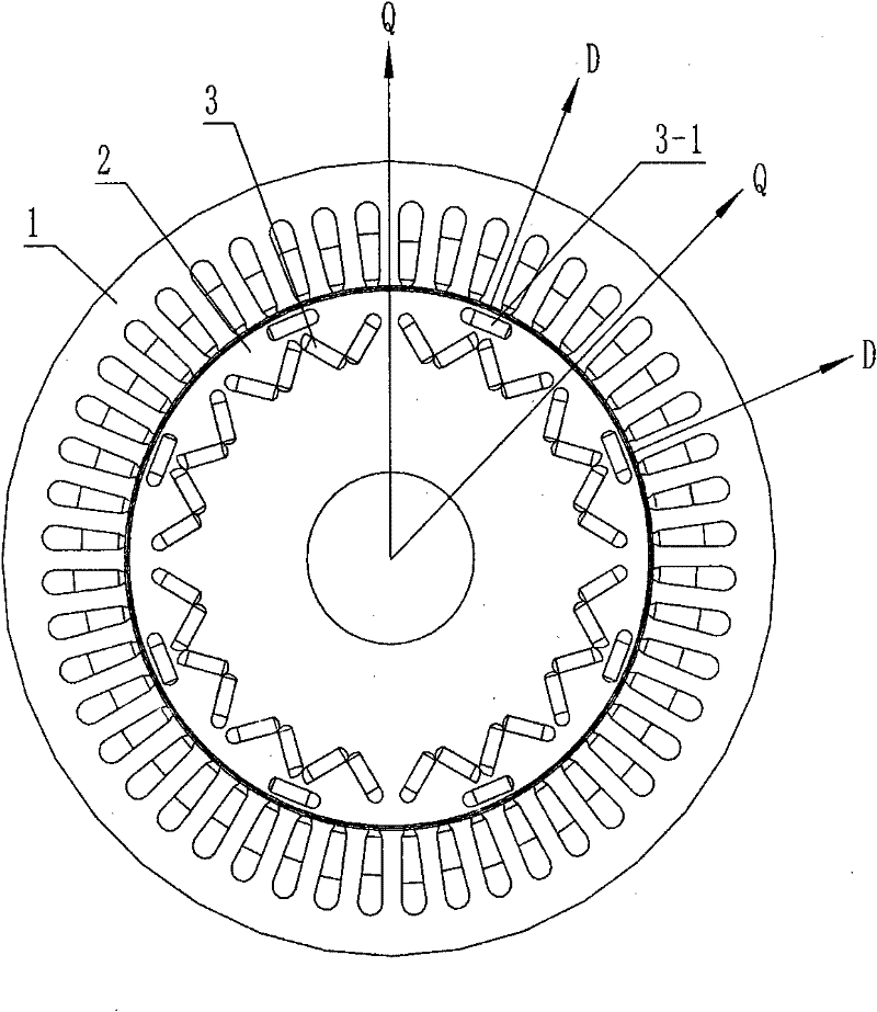
[0020] see figure 1 , figure 2 , this motor can be called W type, the permanent magnets in the rotor are arranged in a "W" shape, and an inline permanent magnet is placed horizontally on it, the purpose is to expand the constant power speed range and reduce the value of the d-axis inductance Ld. The saliency ratio increases, thereby increasing the constant power speed range.

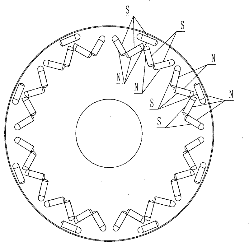
[0021] see figure 2 , the two permanent magnets in the direction of the d-axis have a small gap, and the gap between the two permanent magnets in the direction of the q-axis is slightly wider. This motor has a total of 8 poles, that is, 4 pairs of poles. So 1 / 4 is symmetrical, and it adopts the "micro-bias" theory: the gap between the permanent magnets of the two adjacent Q axes is slightly asymmetrical, which can reduce the pulsating torque output by the motor, and can be used at rated current. Ripple torque is reduced by 8.5%. At the same time, it should be noted that the symmetrical W type wit...


PUM


Abstract

The invention relates to a permanent magnet traction device with wider speed increasing range, which is used for improving the speed increasing performance of a permanent magnet; the technical proposal is that: a plurality of the permanent magnets are embedded in a rotor, the permanent magnets are cuboid and are arrayed along the circumference which is coaxial with the rotor, every four permanent magnets form one group, the cross sections of the four permanent magnets form a W-shaped permanent magnet, and the synthesized magnetizing direction of the same W-shaped permanent magnet is consistent radially, and the synthesized magnetizing direction of the two adjacent W-shaped permanent magnets is opposite, and the W-shaped permanent magnets form a magnetic pole of the rotor; in the invention, the arraying mode of the embedded permanent magnets and a magnetic circuit structure of the rotor are more rational, thereby expanding the constant power speed adjustable range of a permanent magnet synchronization traction motor and improving the weak magnetism speed expanding performance of the permanent-magnet motor; in addition, the permanent magnet traction device has simple structure and is easy to produce and manufacture, the raw material is saved and the efficiency is high.

Description

technical field [0001] The invention relates to a high-performance permanent magnet traction motor, which belongs to the technical field of motors. Background technique [0002] The constant power speed range (CPSR) is an important parameter of the permanent magnet traction motor, which is defined as follows: [0003] [0004] The larger the CPSR value, the stronger the ability of field weakening to expand speed. Theoretically, the speed of the motor can be infinite (see image 3 ), which in fact is not the case. Although electrical engineering designers have worked hard to improve the structure of the motor, especially in the improvement of the structure of the permanent magnet rotor, they have developed a variety of permanent magnet rotors, such as permanent magnet rotors with radial magnetization (that is, the magnetization direction of the permanent magnets is consistent with the radial direction of the rotor) Magnetic synchronous motors have surface type, tradition...

Claims


Application Information

Patent Timeline
Patent Type & Authority Applications(China)
IPC IPC(8): H02K1/27
CPCY02P80/30
Inventor 王艾萌
Owner NORTH CHINA ELECTRIC POWER UNIV (BAODING)
Why Eureka
Try Eureka