Fuel gas supply system and method of ship

A gas supply and ship technology, applied in the container discharge method, container filling method, transportation and packaging, etc., can solve the problems of excess, complex gas supply system, etc., to prevent excessive pressure increase, reduce power requirements, and simplify configuration Effect

Active Publication Date: 2010-06-23
DAEWOO SHIPBUILDING & MARINE ENG CO LTD
View PDF0 Cites 27 Cited by
  • Summary
  • Abstract
  • Description
  • Claims
  • Application Information

AI Technical Summary

Problems solved by technology

This multi-stage compression has the following problems: the gas supply system becomes very complicated and excessive power is required to

Method used


Image

  • Fuel gas supply system and method of ship
  • Fuel gas supply system and method of ship
  • Fuel gas supply system and method of ship

Examples


Embodiment Construction

[0017] Preferred embodiments of the present invention will be described in detail below with reference to the accompanying drawings.

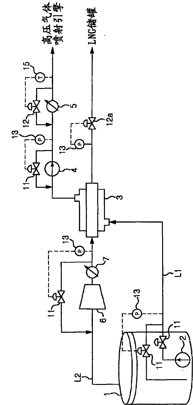
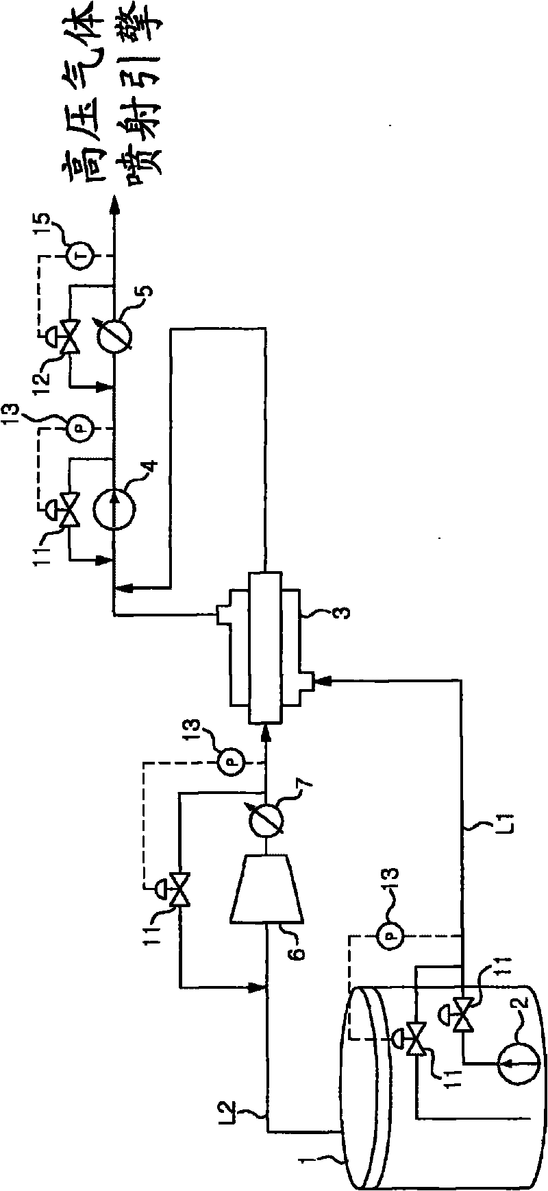
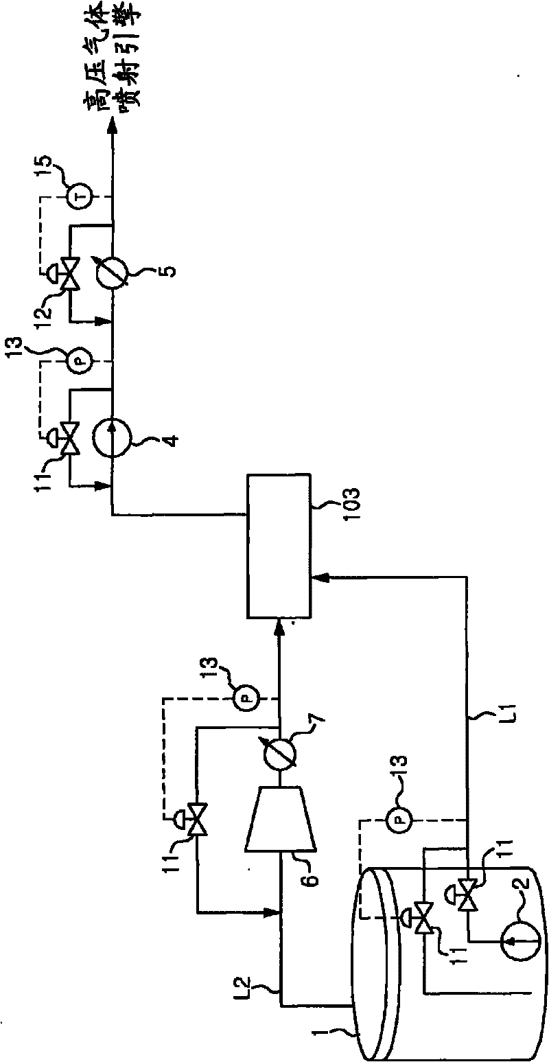
[0018] figure 1 It is a schematic diagram of a gas supply system of a ship according to an embodiment of the present invention. like figure 1 As explained in , the ship's gas supply system supplies gas to the ship's high-pressure gas injection engines.

[0019] figure 1 The gas supply system includes: a gas supply line L1, which is used to supply the LNG extracted from the LNG storage tank 1 of the ship to the high-pressure gas injection engine of the ship; and a heat exchanger 3, which is installed in the middle of the gas supply line L1 In order to exchange heat between the LNG and the boil-off gas extracted from the LNG storage tank 1 .

[0020] The ship may be an LNG carrier. The LNG carrier has an LNG storage tank for storing LNG. In this case, the LNG storage tank 1 is an LNG storage tank.

[0021] In addition, the ship may be a sh...


PUM


Abstract

A fuel gas supply system of a ship is provided for supplying fuel gas to a high-pressure gas injection engine of a ship, wherein LNG is extracted from an LNG tank of the ship, compressed at a high pressure, gasified, and then supplied to the high-pressure gas injection engine.

Description

technical field [0001] The present invention relates to a gas supply system and method for a ship, and more particularly to a ship for efficiently supplying gas from a liquefied natural gas (LNG) tank to a high pressure gas injection engine in a ship Gas supply system and method. Background technique [0002] Generally, natural gas is converted into liquefied natural gas (hereinafter referred to as "LNG") at a low temperature in a liquefaction station, and then transported over a long distance to a destination by an LNG carrier. [0003] Since the liquefaction of natural gas occurs at a cryogenic temperature of -163 degrees Celsius at ambient pressure, LNG is likely to be vaporized even when the temperature of LNG is slightly higher than -163 degrees Celsius at ambient pressure. In an LNG carrier having a thermally insulated LNG storage tank, heat is continuously transferred from the outside to LNG in the LNG storage tank, the LNG is continuously vaporized, and boil-off gas...

Claims


Application Information

Patent Timeline
IPC IPC(8): B63B25/08
CPCF17C2265/033B63J2099/003F17C5/06F17C2227/0185F17C2250/0439F17C2223/047F17C2225/036F17C9/02F17C2270/0105F17C2265/034F17C2225/035B63J99/00F17C2265/037F17C2225/0115F17C2250/0626F17C2223/0161F17C2250/0636F17C2250/0631F17C2223/033F17C2227/0135F17C2250/043F17C2265/066F17C9/00Y02T70/5263F17C2221/033F17C2223/043F17C2260/02F17C2227/0178F17C2227/0393F17C2227/0306F17C2225/0123Y02T70/50F17C5/00
Inventor 权纯斌金南守赵益圭李正汉崔东圭朴铉基
Owner DAEWOO SHIPBUILDING & MARINE ENG CO LTD
Why Eureka
Try Eureka