
Method for manufacturing powder metallurgy supporting seat

A manufacturing method and powder metallurgy technology are applied in the manufacturing field of powder metallurgy bearings, which can solve the problems of reduced welding strength, low elongation rate of powder metallurgy materials, and cracks, and achieve accurate positioning accuracy, good connection strength, and support matrix. high position effect

Active Publication Date: 2010-06-30
NBTM NEW MATERIALS GRP
View PDF0 Cites 13 Cited by
  • Summary
  • Abstract
  • Description
  • Claims
  • Application Information

AI Technical Summary

Problems solved by technology

Under the action of tensile stress, due to the low elongation of powder metallurgy materials, cracks often occur, the welding strength is reduced, and the welding process cannot even be completed.

Method used


Image

  • Method for manufacturing powder metallurgy supporting seat
  • Method for manufacturing powder metallurgy supporting seat
  • Method for manufacturing powder metallurgy supporting seat

Examples


Embodiment Construction

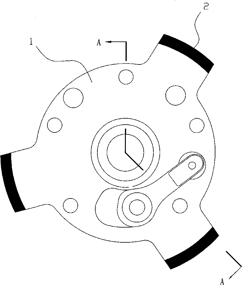
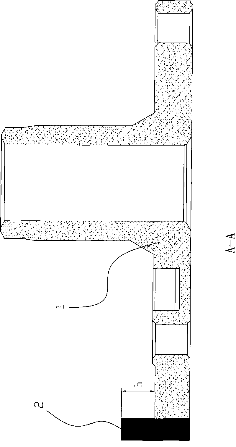
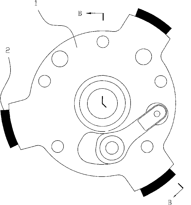
[0025] The present invention will be further described in detail below in conjunction with the accompanying drawings and embodiments.

[0026] Such as Figure 1 to Figure 7 As shown, the manufacturing method of the powder metallurgy support in this embodiment includes the following steps in turn:

[0027] ① Press the support base 1, and press the metal powder into a density of 6.0-7.3g / cm 3 The support base 1 is provided with a structure for placing the transition block 2 on the support base 1; ② process the transition block 2, and process the transition block 2 into a structure that is suitable for placing the transition block 2; ③ place the transition block Put the transition block 2 on the support base 1, and place the solder between the support base 1 and the transition block 2, and then put the support base 1 that has been assembled with the transition block 2 at a temperature of 1050 ~1300°C, and sintering for 5 to 50 minutes in a vacuum or a sintering furnace filled w...


PUM

PropertyMeasurementUnit
densityaaaaaaaaaa
densityaaaaaaaaaa
heightaaaaaaaaaa

Abstract

The invention relates to a method for manufacturing a powder metallurgy supporting seat, which sequentially comprises the following steps: (1) pressing a supporting seat base body (1), and arranging a structure for placing a transition block (2) on the supporting seat base body (1); (2) processing the transition block (2); (3) arranging the transition block on the structure for placing a transition block (2) on the supporting seat base body (1), positioning soldering flux between the supporting seat base body (1) and the transition block (2), and then putting the supporting seat base body (1) assembled with the transition block (2) in to a sintering furnace at the temperature of 1000-1300 DEG C under the condition of vacuum or filling with assistant welding gas sintering atmosphere for sintering for 5-50min; (4) after welding, measuring the size and accuracy to determine whether machining and adjusting are needed for correcting the position of the transition block (2) on the supporting seat base body (1); and (5) carrying out steam treatment on the supporting seat base body (1) welded with the transition block (2); therefore, the manufacturing process of powder metallurgy supporting seat can be completed. Compared with the prior art, as the transition block is welded with the supporting seat base body by a powder metallurgy sintering and soldering method, the supporting seat base body has high position, accurate locating accuracy and good connecting strength; and the whole welding process is simple and easy to operate.

Description

technical field [0001] The invention relates to a manufacturing method of a powder metallurgy bearing, in particular to a manufacturing method of a compressor bearing. Background technique [0002] At present, in the compressor industry, high-power compressors are machined with casting blanks. The method of machining is slow, the utilization rate of materials is low, and the product consistency is poor. The processed products are assembled by welding during assembly. For the welding of cast iron, because it is a conventional material, there are no major process problems in general compressor factories, and the welding quality and welding strength can be better guaranteed. However, for powder metallurgy parts, due to the existence of pores, the number, shape and distribution of pores affect the physical properties of the material such as thermal conductivity, thermal expansion rate and hardenability, etc. These physical properties directly affect the weldability of the mate...

Claims


Application Information

Patent Timeline
Patent Type & Authority Applications(China)
IPC IPC(8): B23P15/00B22F7/00B22F3/16
Inventor 包崇玺毛增光龚晓林
Owner NBTM NEW MATERIALS GRP
Learn More