Dynamic acceleration runway for take-off of carrier aircraft

A Dynamically Accelerated, Carrier-Based Aircraft Technology

Inactive Publication Date: 2010-06-30
刘国忠
View PDF0 Cites 15 Cited by
  • Summary
  • Abstract
  • Description
  • Claims
  • Application Information

AI Technical Summary

Problems solved by technology

[0003] The purpose of the present invention is to provide a dynamic acceleration runway for carrier-based aircraft to take off, to solve the problem of large impact force on carrier-based aircraft, too long take-off line and carrier-based aircraft movement when carrier-based aircraft takes off using the existing take-off mode. The problem of poor flexibility

Method used


Image

  • Dynamic acceleration runway for take-off of carrier aircraft
  • Dynamic acceleration runway for take-off of carrier aircraft
  • Dynamic acceleration runway for take-off of carrier aircraft

Examples


specific Embodiment approach 1

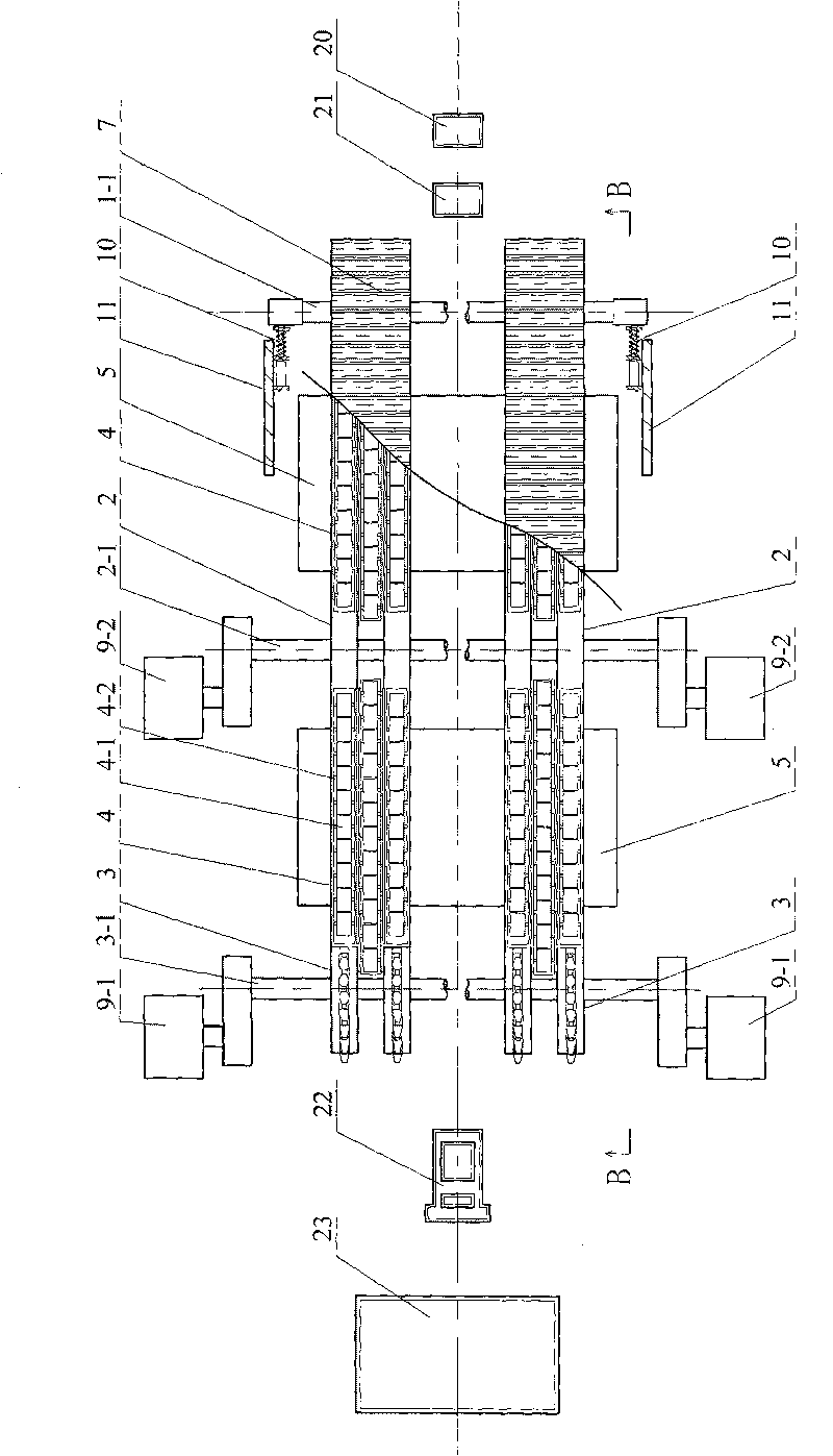
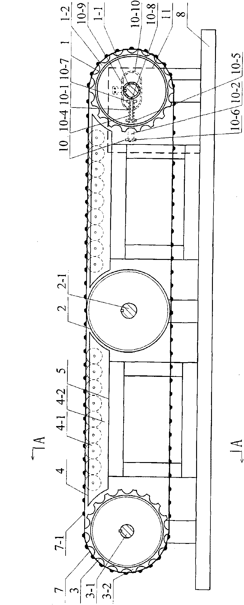
[0007] Specific implementation mode one: combine figure 1 , figure 2 and Figure 4 Illustrate the dynamic acceleration runway for carrier aircraft take-off of the present embodiment, it comprises transmission mechanism, driving device, two crawler belts 7 and crawler belt supporting device, and described transmission mechanism is made of two drive sprocket groups 3, drive axle 3 -1. Two driven sprocket sets 1 and driven wheel shafts 1-1, the crawler support device consists of two large load-bearing wheel sets 2, large load-bearing wheel shafts 2-1, four wheel-type supports 4 and wheel-type The supporting body bracket 5 is formed, the driving wheel shaft 3-1, the driven wheel shaft 1-1 and the large load-bearing wheel shaft 2-1 are arranged in parallel and the axes of the three are located on the same horizontal plane, and one is respectively installed at the two ends of the driving wheel shaft 3-1. Drive sprocket group 3, a driven sprocket group 1 is installed at both ends ...

specific Embodiment approach 2

[0008] Specific implementation mode two: combination figure 1 and figure 2 Illustrate the dynamic acceleration runway used for carrier aircraft take-off in this embodiment, the drive device includes two drive wheel drive motors 9-1 and two load wheel drive motors 9-2, the two drive wheel drive motors 9 -1 is arranged at both ends of the driving wheel shaft 3-1 and is connected to the transmission of the two driving sprocket sets 3, and two load-bearing wheel drive motors 9-2 are arranged at both ends of the large load-bearing wheel shaft 2-1 and connected Wheel set 2 transmission connection. Other components and connections of this embodiment are the same as those in the first embodiment.

specific Embodiment approach 3

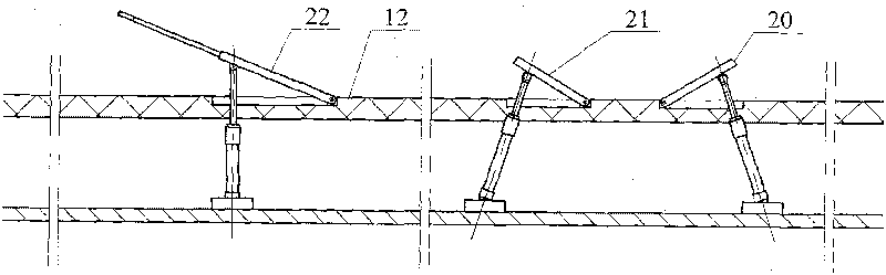
[0009] Specific implementation mode three: combination figure 1 and figure 2 Illustrate the dynamic acceleration runway used for carrier aircraft take-off of the present embodiment, each driving sprocket set 3 is made up of two driving sprockets, and each driven sprocket set 1 is made up of two driven sprockets, Each large load-bearing wheel set 2 is made up of two large load-bearing wheels. The two drive wheel drive motors 9-1 and the two load wheel drive motors 9-2 are respectively connected to frequency converters, and the motors and frequency converters in the driving device can be fixed on the frame under the deck 12 of the aircraft carrier. In order to keep the aircraft in the best static acceleration state on the runway, it is necessary to maximize the forward instantaneous speed of the aircraft to be consistent with the backward instantaneous speed of the runway. Inputting the data of the speed change of the aircraft every second during the runway runway into the co...


PUM


Abstract

The invention discloses a dynamic acceleration runway for the take-off of a carrier aircraft, in particular relates to a runway for the take-off of a carrier aircraft and specially relates to a dynamic acceleration runway for the take-off of a carrier aircraft, aiming to solve the problems of large impact force to the carrier aircraft, overlong take-off line and poor action flexibility of the carrier aircraft existing when the carrier aircraft takes off by utilizing the traditional taking off mode. A driving wheel shaft, a driven wheel shaft and a heavy-bearing wheel shaft are arranged in parallel, and axle centers of the three wheel shafts are on the same horizontal plane, wherein both ends of the driving wheel shaft are respectively provided with a driving chain wheel set, both ends of the driven wheel shaft are respectively provided with a driven chain wheel set, and both ends of the heavy-bearing wheel shaft are respectively provided with a heavy-bearing wheel set; the two driving chain wheel sets are connected with two corresponding driven chain wheel sets through a caterpillar band through transmission; each wheel type supporting body is adhered to the lower end face of the caterpillar band; and a plurality of light-bearing wheels are horizontally and uniformly distributed and embedded on a light-bearing wheel framework. The invention is suitable for a run-up system of the short-distance take-off or the vertical landing of the carrier aircrafts on light aircraft carriers and amphibious attack ships.

Description

technical field [0001] The invention relates to a runway for carrier-based aircraft to take off, in particular to a dynamic acceleration runway for carrier-based aircraft to take off. Background technique [0002] An aircraft carrier is a large surface ship with carrier-based aircraft as its main combat weapon. It has both offensive and defensive capabilities, strong combat capabilities, and can perform a variety of tactical tasks. At present, there are two types of take-off methods for carrier-based aircraft: steam catapult take-off and jump-flying deck take-off. Among them, steam catapult take-off uses pistons to drive the aircraft to accelerate to a sufficient speed, and releases the aircraft through appropriate devices. Due to the weight of the steam catapult Yamato occupies a large space, the impact of steam ejection is large, and the fatigue damage caused to the aircraft structure is relatively heavy, so the service life of the carrier-based aircraft is shorter than th...

Claims


Application Information

Patent Timeline
Patent Type & Authority Applications(China)
IPC IPC(8): B64F1/04
Inventor 刘国忠
Owner 刘国忠
Why Eureka
Try Eureka