
Combined structure and method of light fitting component

A combined structure and lamp technology, applied in the direction of electrical components, electric solid devices, semiconductor devices, etc., to achieve the effects of eliminating damage and light decay of light-emitting array chips, good thermal conductivity, and convenient assembly

Inactive Publication Date: 2012-03-14
吕绍裕
View PDF4 Cites 0 Cited by
  • Summary
  • Abstract
  • Description
  • Claims
  • Application Information

AI Technical Summary

Problems solved by technology

[0003] The main technical problem to be solved by the present invention is to overcome the above-mentioned defects in the prior art, and provide a combination structure and method of lamp components. The thermal conductivity of the array chip is good, which can eliminate the problems and shortcomings of the luminescent array chip damage and light decay caused by the poor thermal conductivity of the luminescent array chip due to the poor thermal conductivity of the thermally conductive adhesive, and further improve the reliability of the luminescent array chip as a light source body and reliability

Method used


Image

  • Combined structure and method of light fitting component
  • Combined structure and method of light fitting component
  • Combined structure and method of light fitting component

Examples


Embodiment Construction

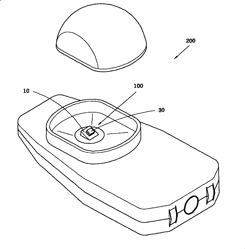
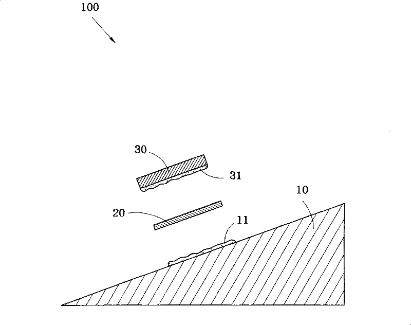
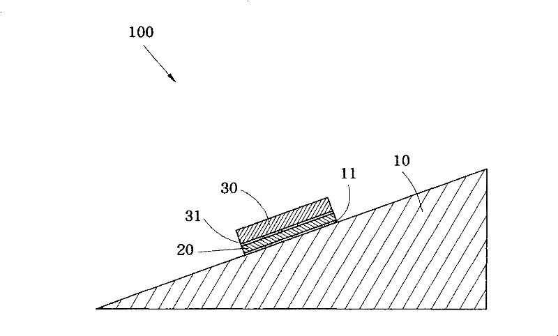
[0044] A luminous array chip 30 is composed of an array of several emitting diode components. The bottom surface of the luminous array chip 30 is combined with the first metal glue layer 31.As an example, the second metal glue layer 31 combines the other side of the above metal film 20, which makes the luminous array chip 30 combined with the surface of the lamp base 10.

[0045] Please cooperate again image 3 Show, the first metal glue layer 11, the first metal glue layer 11, the metal film 20, and the luminous array chip 30 of the lamp base 10 in the combination structure of the present invention can use various hot melt methods to light upThe array chip 30 is firmly combined on the surface of the lamp base 10, and the embodiment of its combination will be clarified in the following combination method steps.

[0046] Please cooperate again Figure 4 As well as Figure 5 and Figure 6 Show, Figure 4 For the implementation step flow chart of the combination of chip combination method...


PUM


Abstract

The invention relates to a combined structure and a method of a light fitting component. The combined structure comprises a light fitting base, at least metal film and a light-emitting array chip, wherein the light fitting base is arranged at the inner part of a light-emitting diode light fitting; one face of the metal film is jointed with a first metal glue layer of the surface of the light fitting base; and the light-emitting array chip is a component comprising a plurality of light-emitting diode components. The combined method comprises the following steps of: gluing metal glue on the surface of the metal film and coating a layer of the first metal glue layer on the surface of the light fitting base; connecting the light fitting base with the anode of a power supply; connecting the metal film with a cathode of the power supply; gluing the metal glue on the light-emitting array chip, and coating a layer of a second metal glue layer on the bottom of the light-emitting array chip; jointing the light-emitting array chip with the metal film; and jointing the light-emitting array chip with the light fitting base. The invention eliminates the problem and shortcoming of damage of the light-emitting array chip and light decay caused by poor heat conduction of joint of heat-conducting glue with the light-emitting array chip, and enhances the reliability of the light-emitting array chip as a light source body.

Description

Technical field [0001] The invention involves a combination structure and method of a lamp component. Background technique [0002] The existing light -emitting diode lamps are widely used in outdoor public lighting and interior decoration lighting to provide the function of lighting and energy saving and environmental protection.The heating glue is fixed to fix the chip of the emitting diode array. The thermal conductivity is used as the connector to fit the chip of the emitting diode array, which can easily make the chip chip of the emitting diode in poor heat conduction, resulting in the damage and light decay of chip chip of the emitting diode array array.(Optic Loss) problems and disadvantages of the emitting diode array chip decreased by the light source body trust and reliability when applied to the lighting device. Invention content [0003] The main technical problem to be solved by the present invention is to overcome the above -mentioned defects of existing technolo...

Claims


Application Information

Patent Timeline
Patent Type & Authority Patents(China)
IPC IPC(8): F21S2/00F21V21/00F21V29/00H01L23/373F21Y101/02F21V29/503F21V29/85
Inventor 吕绍裕
Owner 吕绍裕
Learn More