Eureka AIR delivers breakthrough ideas for toughest innovation challenges, trusted by R&D personnel around the world.

Sectional evaporation-compression vapor compression heat pump

A compression heat pump, segmented compression technology, applied in heat pumps, lighting and heating equipment, refrigeration components, etc., can solve the problems of low utilization rate of waste heat and low performance index of units

Inactive Publication Date: 2010-06-30
李华玉
View PDF0 Cites 11 Cited by
  • Summary
  • Abstract
  • Description
  • Claims
  • Application Information

AI Technical Summary

Problems solved by technology

[0004] Therefore, when the waste heat resource—that is, the refrigerated medium—is relatively small, the temperature range is large, and the total load of waste heat utilization is large, the vapor compression heat pump unit with a single evaporator corresponding to a single compressor has a relatively simple structure. , but the performance index of the unit is low, and the waste heat utilization rate is not high; the vapor compression heat pump unit with a single evaporator staged compression and interstage cooling still cannot effectively solve this problem

Method used


Image

  • Sectional evaporation-compression vapor compression heat pump
  • Sectional evaporation-compression vapor compression heat pump
  • Sectional evaporation-compression vapor compression heat pump

Examples


Embodiment Construction

[0033] The present invention will be described in detail below in conjunction with the accompanying drawings and examples.

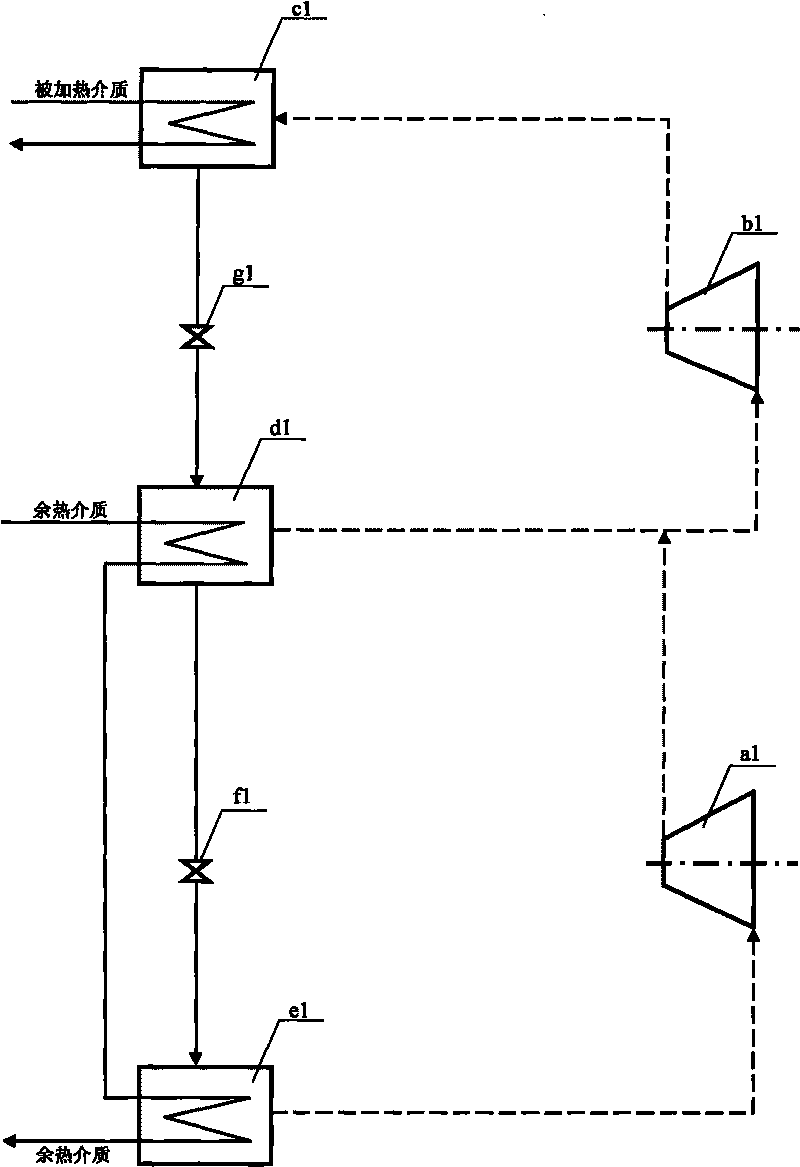
[0034] figure 1 The shown two-stage evaporation-two-stage compression vapor compression heat pump that provides refrigerant vapor to the condenser by the second compressor is implemented as follows:

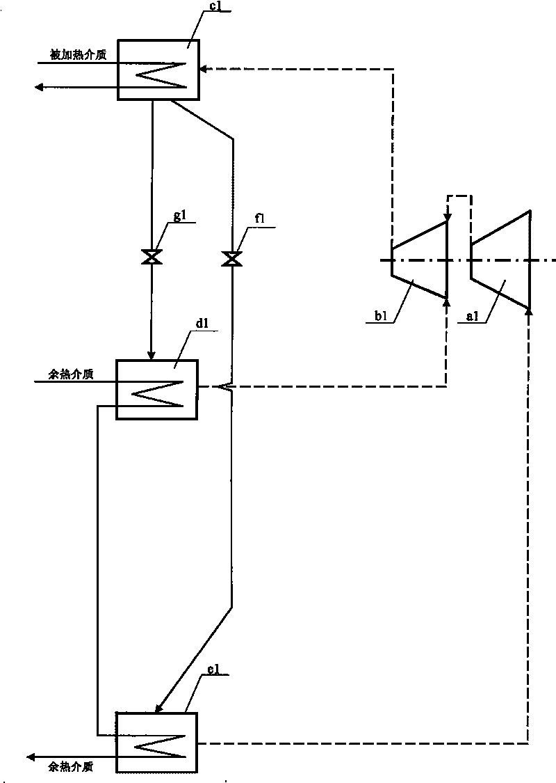
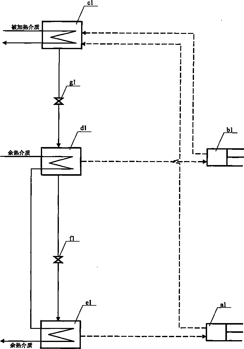
[0035] ① Structurally, the first compressor, the second compressor, the condenser, the high-temperature evaporator, the low-temperature evaporator, the first throttling valve and the second throttling valve constitute the refrigerant vapor provided by the second compressor to the condenser. The two-stage evaporation-two-stage compression vapor compression heat pump; the second compressor b1 has a refrigerant vapor pipeline connected to the condenser c1, and the condenser c1 also has a refrigerant liquid pipeline connected to the high-temperature evaporator through the second throttle valve g1 d1 and the heated medium pipeline communicate with the outside, ...


PUM


Abstract

The invention provides a sectional evaporation-compression vapor compression heat pump, belonging to the technical field of residual-heat utilization and heat pump / refrigeration. The vapor compression heat pump aims at overcoming the defects of a vapor compressor provided with a single evaporator when a residual-heat medium has large temperature variation range, and provides a vapor compression machine set which comprises more than two compressors, more than two evaporators, a condenser, a throttle valve and the like and realizes sectional evaporation-compression; low temperature section evaporation-compression can be realized by the low temperature evaporator and the first compressor; high temperature section evaporation-compression can be realized by the high temperature evaporator and the second compressor; the residual-heat medium firstly flows through heating refrigerant liquid of the high temperature evaporator to become refrigerant vapor to be provided for the second compressor, and then flows through heating refrigerant liquid of the low temperature evaporator to become refrigerant vapor to be provided for the first compressor after the temperature is lowered, the first compressor provides the refrigerant vapor for the condenser or the second compressor; and the heat of the heated medium is absorbed by the condenser when the medium flows through the condenser. The sectional evaporation-compression vapor compression heat pump reduces residual-heat transmission temperature difference, improves the performance index of the machine set, and can reduce the power consumption of the machine set when the residual-heat medium has large temperature variation range.

Description

technical field [0001] The utility model belongs to the field of waste heat utilization and heat pump / refrigeration technology. Background technique [0002] Vapor compression heat pump is one of the main equipment in waste heat application, which can bring many benefits such as energy saving, environmental protection and economy. Vapor compression heat pumps are mainly composed of basic components such as compressors, condensers, throttle valves, and evaporators. The waste heat is obtained mainly by the vaporization and heat absorption of the working fluid in the evaporator. In the case of relatively few waste heat resources, the temperature drop of the waste heat medium will be large. At this time, if a vapor compression heat pump with a single evaporator is used, problems such as high compression ratio, low volumetric efficiency, and reduced performance index of the unit will be caused. . In order to improve the performance index of the unit, the technical measures of s...

Claims


Application Information

Patent Timeline
IPC IPC(8): F25B30/02
Inventor 李华玉
Owner 李华玉
Why Eureka
Eureka Blog
Learn More