Method and device for producing hydrocarbon by Fishcer-Tropsch reaction of synthesis gas

A technology of Fischer-Tropsch reaction and reaction hydrocarbon production, which is applied in the field of chemical engineering and can solve the problems of large-scale limitation and reduction of effective utilization of catalysts, etc.

Inactive Publication Date: 2009-10-21
杭州林达化工科技有限公司
View PDF1 Cites 13 Cited by
  • Summary
  • Abstract
  • Description
  • Claims
  • Application Information

AI Technical Summary

Problems solved by technology

In addition, although the SSPP slurry bed reactor of Sasol Company in South Africa is beneficial to heat transfer to make the temperature in the reactor uniform, it is limited by the gas phase, liquid phase and solid phase (catalyst) mass transfer resistance, which reduces the effective utilization of the catalyst and is limited in size.

Method used


Image

  • Method and device for producing hydrocarbon by Fishcer-Tropsch reaction of synthesis gas
  • Method and device for producing hydrocarbon by Fishcer-Tropsch reaction of synthesis gas
  • Method and device for producing hydrocarbon by Fishcer-Tropsch reaction of synthesis gas

Examples


Embodiment 1

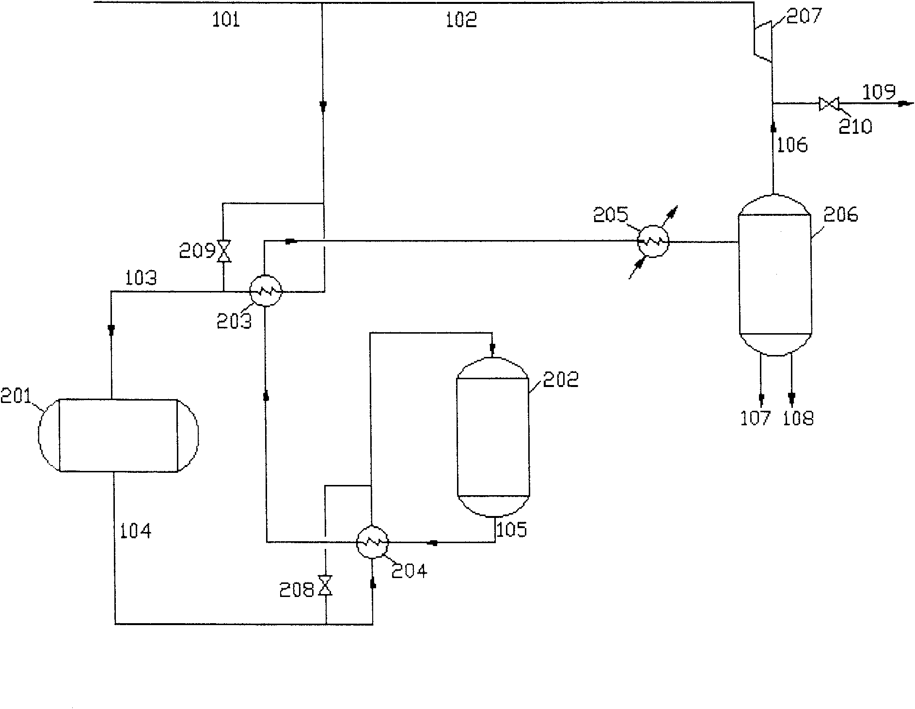
[0031] Embodiment 1: Gasoline production process with synthesis gas as figure 1 , the Fischer-Tropsch synthesis reactor 201 adopts such as Figure 4 Horizontal Fischer-Tropsch synthesis reactor with a diameter of 3.9 meters and a built-in ultrafine Fe-Mn Fischer-Tropsch catalyst of 150M 3 , the hydrocarbon upgrading reactor 202 adopts a segmented adiabatic fixed-bed reactor with a diameter of 3.8 meters and a 100M ZSM-5 molecular sieve catalyst inside 3 , the synthesis gas compressed to 5 MPa merges with the recycle gas, and is heated to 210°C up and down into the Fischer-Tropsch synthesis reactor 201, and the Fischer-Tropsch synthesis reaction is carried out on the Fischer-Tropsch catalyst layer at a temperature of about 240°C. The heat of reaction is absorbed by the water in the two sets of horizontal water pipes in the reactor to produce steam, the pressure of the steam drum 71 is about 1Mpa lower than the steam pressure in the 72, and the heat exchange with the outlet gas...

Embodiment 2

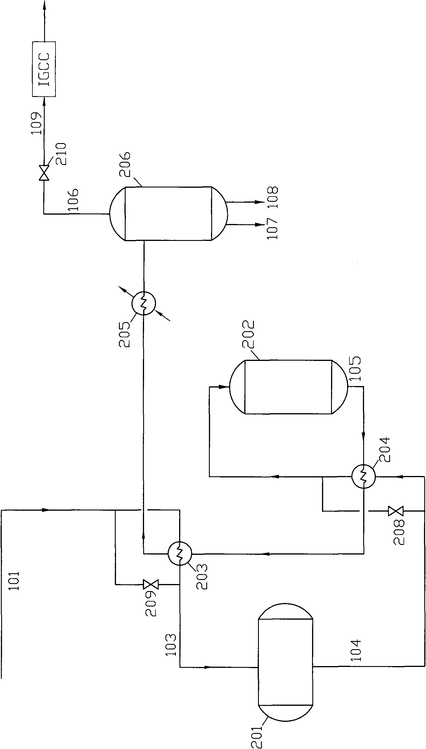
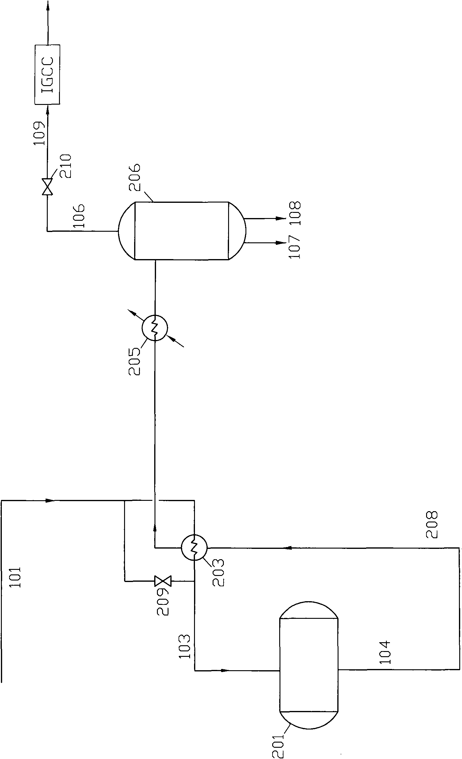
[0034] Embodiment 2: use syngas one-step method to make gasoline combined with IGCC production process see figure 2 , the Fischer-Tropsch synthesis reactor 201 adopts such as Figure 4 Fischer-Tropsch synthesis reactor with a diameter of 5.2 meters and a built-in iron-based or cobalt-based Fischer-Tropsch catalyst of 130M 3 , ZSM-5 molecular sieve catalyst 90M 3 , the synthetic gas compressed to 5.5MPa is heated to 220°C and enters the Fischer-Tropsch synthesis reactor 201, and at a temperature of about 250°C, Fischer-Tropsch synthesis and hydrocarbon upgrading reactions are carried out on the composite Fischer-Tropsch catalyst layer. The heat of reaction is absorbed by the water in the two sets of horizontal water tubes in the reactor to by-produce steam. The water vaporization pressure difference between the two sets of heat exchange tubes is about 1Mpa, and the conversion rate of CO in the gas exiting the Fischer-Tropsch synthesis reactor 201 reaches 78%. In this example...


PUM


Abstract

The invention relates to a method for producing hydrocarbon by Fishcer-Tropsch reaction of synthesis gas, comprising the following steps: firstly, under the pressurizing, the synthesis gas containing hydrogen and carbon monoxide carries out Fishcer-Tropsch synthetic reaction in a Fishcer-Tropsch synthetic reactor 201 which has at least two zones capable of independently adjusting vaporizing temperature of cooling medium and preferably adopts a water cooling heat exchanging pipe set with the front-low rear-high temperature; tower reaction gas is cooled and separated or enters a hydrocarbon modifying reactor 202 with molecular sieve to carry out hydrocarbon modification, final reaction gas is cooled to separate hydrocarbon, water and unreacted synthesis gas, the separated synthesis gas is discharged to gas / steam for integral circulation generating (IGCC), or the separated synthesis gas is used as circulation synthesis gas to be mixed with the synthesis gas of raw materials except a little discharged separated synthesis gas, and the Fishcer-Tropsch reaction and product separation are carried out again.

Description

technical field [0001] The invention relates to a method and equipment for producing hydrocarbons by using synthesis gas Fischer-Tropsch reaction, which belongs to the field of chemical engineering. Background technique [0002] The method of coal or natural gas to oil can be produced by gasification of coal or conversion of natural gas 2 , CO, CO 2 The synthetic gas produced by the Fischer-Tropsch (F-T) reaction produces liquid hydrocarbons, gasoline or diesel oil, etc. At present, the industrialized devices in the world are mainly South African Sasol Company, and the core technology reactor in the Fischer-Tropsch reaction has a shell-and-tube reactor for the Sasol-I plant. (See Gao Jinsheng edited "Coal Liquefaction Technology" Chemical Industry Press, P390), in the catalyst packing tube, the catalyst packing coefficient of this tower is small, and the tower pressure drop is big, Sasol II and Sasol III etc. also adopt reactors such as circulating fluidized bed, although ...

Claims


Application Information

Patent Timeline
IPC IPC(8): C10G5/00
Inventor 楼韧楼寿林
Owner 杭州林达化工科技有限公司
Why Eureka
Try Eureka