Case-type multi-shell-pass countercurrent speedup type shell and tube heat exchanger
A shell-and-tube heat exchanger, multi-shell-side technology, applied in the direction of heat exchanger type, heat exchanger shell, indirect heat exchanger, etc., can solve the problem of low heat transfer coefficient of heat exchanger and low fluid velocity on the shell side , large diameter of the shell, etc., to achieve the effect of compact arrangement, reduction of charging amount, and reduction of heat transfer temperature difference
- Summary
- Abstract
- Description
- Claims
- Application Information
AI Technical Summary
Problems solved by technology
Method used
Image

Examples
Embodiment 1
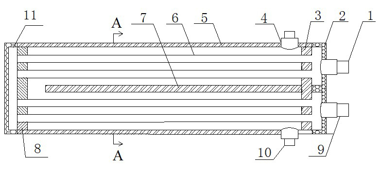
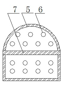
[0034] Such as figure 1 As shown, the shell-and-shell multi-shell-side countercurrent speed-up type shell-and-tube heat exchanger includes a shell 5, and tube sheets I3 and tube sheets II8 are arranged at both ends of the shell, and the tube box 2 is connected to the outside of the tube sheet I3 and A partition is arranged inside, an end cover 11 is provided at the other end of the shell, and a heat exchange tube 6 is arranged inside the shell, the heat exchange tube is a straight tube heat exchange tube, and the heat exchange tube runs through the tube plate I3 and the tube plate II8 It communicates with the pipe box and end cap at both ends. The pipe box 2 is provided with a pipe interface I1 and a pipe interface II9, and a pipe interface III4 and a pipe interface IV10 are respectively arranged on the upper and lower parts of the housing. The heat exchanger shell has an upper circle and lower structure, that is, the upper part is a semi-cylindrical shape, and the lower part...
Embodiment 2
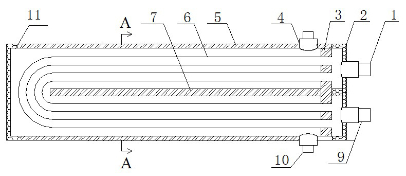
[0037] Such as figure 2 As shown, this embodiment is based on the structure of the embodiment, and the heat exchange tube is a U-shaped tube.
Embodiment 3
[0039] Such as image 3 As shown, the example is in image 3 On the basis of the structure shown, a transverse speed-increasing disturbance deflector 12 is arranged in the casing 5 . The shape of the horizontal speed-increasing disturbance deflector is the same as the cross-sectional shape of the fluid flow channel outside the tube formed in the casing, and there is a channel gap at one end of the horizontal speed-increasing deflector, and a number of holes are opened on the surface of the deflector for supporting The tube hole of the heat exchange tube.
PUM
 Abstract
Description
Claims
Application Information