

Synchronous display device, stacking splicing display system and synchronous display method thereof
A technology of synchronous display and display card, applied in identification devices, components of TV systems, digital output to display devices, etc., can solve problems such as untimely response time, interrupted display output, blurry screen, etc., to improve accuracy and continuity. sexual effect
- Summary
- Abstract
- Description
- Claims
- Application Information
AI Technical Summary
Problems solved by technology
Method used
Image

Examples
Embodiment 1
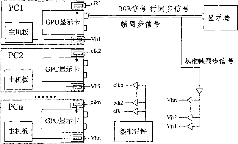
[0026] see figure 2 As shown, it is a schematic structural diagram of Embodiment 1 of the synchronous display device of the present invention.
[0027] Such as figure 2 As shown, in this example, multiple PCs are used as an example for splicing display. It is assumed that each PC includes only one display card. As shown in the figure, the synchronous display device includes a synchronous control circuit and two The above PCs, wherein the synchronization control circuit includes a frame synchronization control circuit and a reference clock generation circuit, each PC includes a motherboard and a display card, and each display card is inserted and connected to the motherboard of the PC where it is located , the clock signal input terminals of the display cards of all PCs are connected with the signal output terminals of the reference clock generation circuit, and the signal input terminals of the motherboards of all PCs are connected with the signal output terminals of the fr...
Embodiment 2
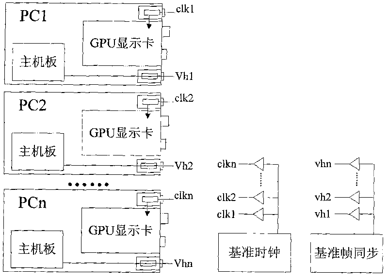
[0048] In the above description of Embodiment 1, an independent frame synchronization control circuit generates a reference frame synchronization signal for frame synchronization adjustment. In fact, the frame synchronization of the display channel of one of the display cards can also be used. The signal is used as a reference frame synchronization signal, and the frame synchronization adjustment is performed accordingly, so that it is not necessary to specially generate a reference frame synchronization signal.
[0049] see Figure 4 As shown, it is a schematic structural diagram of Embodiment 2 of the synchronous display device of the present invention. In this example, the main difference from the above-mentioned Embodiment 1 is that in this embodiment, the frame of the display channel of one of the display cards is selected. The synchronization signal serves as a reference frame synchronization signal.
[0050] Such as Figure 4As shown, in the synchronous display device...
Embodiment 3
[0056] see Figure 4 As shown, it is a schematic structural diagram of Embodiment 3 of the synchronous display device of the present invention, which is the simplest method among the above-mentioned synchronous control methods using a specially designed synchronous control circuit.
[0057] In the illustration, the main control part is taken as an example of a single-chip microcomputer or FPGA for illustration. The reference clock signals clk1 and clk2 generated by the reference clock generation circuit are respectively connected to the clocks of the corresponding two display cards (not shown in the figure). At the input terminal, Vh1 represents the frame synchronization signal from display channel 1, and Vh2 represents the frame synchronization signal from display channel 2. Vh1 is used as the reference frame synchronization signal, and FPGA performs a time comparison between Vh1 and Vh2 to compare the difference between the two , and judge whether the difference value exceed...
PUM
 Abstract
Description
Claims
Application Information