Backlight source, manufacture method thereof, liquid crystal display and liquid crystal television

A manufacturing method and backlight technology, which are applied in the manufacture of discharge tubes/lamps, ships or leading wires, and instruments, can solve the problems of difficult operation, many assembly processes, and unfavorable thinning, so as to reduce materials, Effect of cost reduction and simplification of assembly process

Inactive Publication Date: 2010-06-30
BOE TECH GRP CO LTD +1
View PDF0 Cites 3 Cited by
  • Summary
  • Abstract
  • Description
  • Claims
  • Application Information

AI Technical Summary

Problems solved by technology

Moreover, more materials are used for the backlight source, which leads to more assembly processes and is not easy to operate.
For example, the side-lit backlight needs to design the dots of the light guide plate and print the dots of the light guide plate to change the side light to the surface light. Among them, the optical picture is difficult to control; the direct-lit backlight needs many CCFLs or many LED lights. Meet the light source requirements, resulting in high cost and not conducive to thinning

Method used


Image

  • Backlight source, manufacture method thereof, liquid crystal display and liquid crystal television
  • Backlight source, manufacture method thereof, liquid crystal display and liquid crystal television
  • Backlight source, manufacture method thereof, liquid crystal display and liquid crystal television

Examples


Embodiment Construction

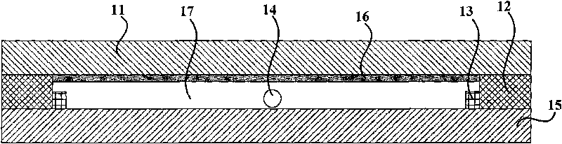
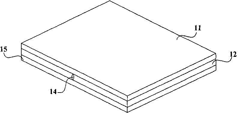
[0028] Figure 1A It is a schematic cross-sectional structure diagram of an embodiment of a backlight source of the present invention. Figure 1B for Figure 1A Schematic diagram of the three-dimensional structure. Such as Figure 1A , Figure 1B As shown, the backlight includes: a face glass 11, a glass frame 12, an electrode 13, an exhaust pipe 14 and a back glass 15. The face glass 11 is coated with phosphor 16; the glass frame 12 is sealed to the side of the face glass 11 coated with phosphor 16; the electrode 13 is sealed in the glass frame 12; the exhaust pipe 14 is sealed to the glass frame 12; the back glass 15 is made of quartz glass, sealed on the glass frame 12, and forms a cavity 17 with the face glass 11; the exhaust pipe 14 is in a closed state when the cavity 17 becomes vacuum.

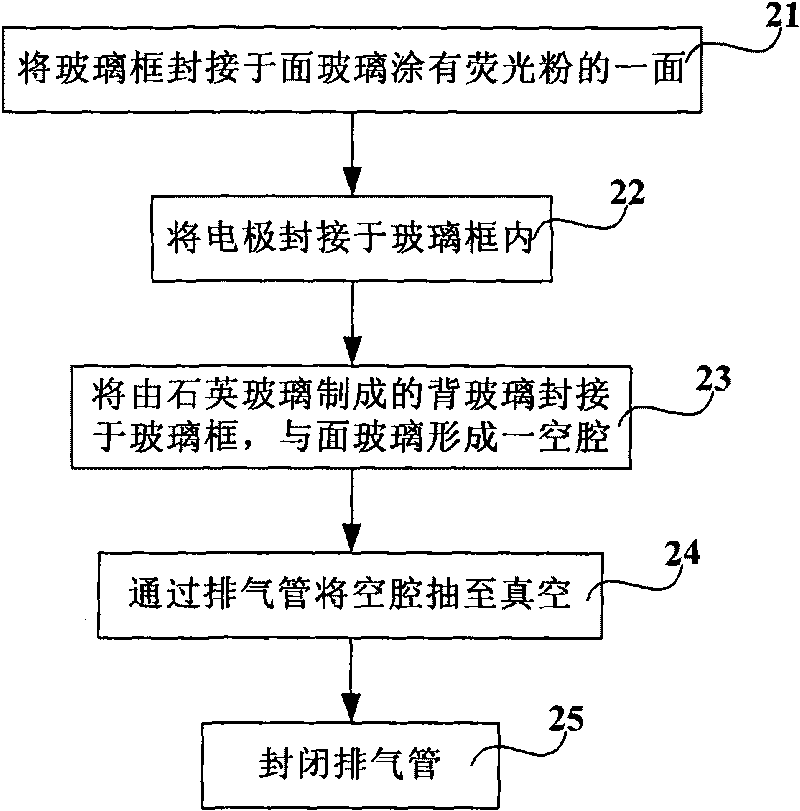
[0029] In this embodiment, the backlight is formed by the face glass, the back glass and the flat glass cavity coated with phosphor powder in the glass frame, which can emit a uniform white l...


PUM


Abstract

The invention relates to a backlight source, a manufacture method thereof, a liquid crystal display and a liquid crystal television. The backlight source comprises facade glass, a glass frame, an electrode, a vent pipe and back glass, wherein the facade glass is coated with fluorescent powder; the glass frame is sealed at the side of the surface glass coated with the fluorescent powder; the electrode is sealed in the glass frame; the vent pipe is sealed in the glass frame; the back glass is made of quartz glass and sealed on the glass frame and forms a cavity with the facade glass; and the vent pipe is in a sealing state under the condition that the cavity is vacuumed. The method comprises the following steps of: sealing the glass frame at the side of the facade glass coated with the fluorescent powder; sealing the electrode in the glass frame; sealing the back glass made of the quartz glass on the glass frame and forming the cavity with the facade glass; pumping the cavity to vacuum through the vent pipe; and sealing the vent pipe. The display and the television are provided with the backlight source. The plane glass cavity which is internally coated with the fluorescent powder and formed by the facade glass, the back glass and the glass frame meets the requirement of the light source and reduces the cost meanwhile.

Description

Technical field [0001] The present invention relates to the technical field of liquid crystal display, in particular to a backlight source, a method for manufacturing the backlight source, a liquid crystal display and a liquid crystal television. Background technique [0002] At present, in flat panel display (Flat Panel Display, hereinafter referred to as FPD) technology, liquid crystal display (Liquid Crystal Display, hereinafter referred to as LCD) devices occupy a dominant position, and transmissive liquid crystal displays are the mainstream of current LCD technology. Since the LCD itself does not emit light, the backlight is essential for transmissive LCDs. [0003] According to the different distribution positions of the light source, the backlight source can be divided into an edge type backlight source and a direct type backlight source. The backlight used in the liquid crystal display is mainly edge-lit backlight, and the direct-lit backlight is mainly used in LCD TVs. [...

Claims


Application Information

Patent Timeline
Patent Type & Authority Applications(China)
IPC IPC(8): H01J63/00H01J63/02H01J9/00H01J9/24G02F1/13357
Inventor 杨东升刘飞
Owner BOE TECH GRP CO LTD
Why Eureka
Try Eureka