Metal wire laying method

A laying method and metal wire technology, applied in the direction of electrical components, antennas, etc., can solve the problems of difficulty in ensuring accuracy, low efficiency, and inability to lay metal wires, and achieve the effect of high laying accuracy and fast speed

Active Publication Date: 2010-06-30
XIAN AIRCRAFT IND GROUP
View PDF3 Cites 9 Cited by
  • Summary
  • Abstract
  • Description
  • Claims
  • Application Information

AI Technical Summary

Problems solved by technology

[0004] In order to overcome the shortcomings of the existing laying method, such as low efficiency, difficulty in ensuring accuracy, and the inability to lay metal wires on the surface of complex shapes with large curvature, concave and convex, the present invention provides a method for laying metal wires.

Method used


Image

  • Metal wire laying method
  • Metal wire laying method
  • Metal wire laying method

Examples


Embodiment Construction

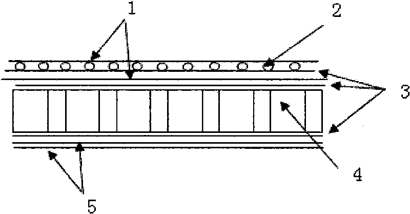
[0019] This embodiment is a certain antenna reflector metal wire laying process.

[0020] The structure of the antenna reflector is a sandwich structure of composite materials, including a honeycomb core 4 , a metal wire 2 , an inner skin 1 and an outer skin 5 . The honeycomb core 4 is made of NOMEX honeycomb core, the skin panel is made of prepreg, and the diameter of the metal wire 2 is 0.2.

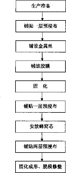
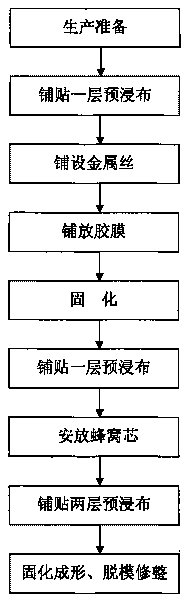
[0021] The laying process of this embodiment is:

[0022] 1. First write the program for laying the metal wire 2 according to the electrical design requirements.

[0023] 2. Apply a release agent on the surface of the reflector molding tool; spread a layer of aramid fiber prepreg on the surface of the reflector molding tool as the first outer skin 5 of the reflector. Position and fix the reflector forming tool with the prepreg laid on the working table of the CNC machine tool, and position and align it according to the reference hole on the reflector forming tool; clamp the metal wir...


PUM


Abstract

The invention discloses a metal wire laying method, which is a process method for paying off along the coordinate system direction of the body surface and grooving and laying by adopting a numerical control machine through a metal wire laying device, and comprises the following steps: paying off along the coordinate system direction of the body surface and grooving and laying a metal wire (2) on the surface of a device for laying, molding and positioning; and after fixing the metal wire (2), molding the meal wire (2) on the device for laying, molding and positioning and transferring the metalwire (2) to the body surface of the product through laying, vacuum-pumping and curing on the surface of a prepreg. By using the characteristics of the numerical control machine, parallel lines or oblique lines in equivalent width / space change can be laid without being limited by the body, the metal wires which have a diameter phi of 0.1 to 1 mm and are made of different soft materials can be laidon the surface of any body, laying precision and speed are high, and the metal wire laying method effectively solves the problem that the metal wire cannot be laid on the surface of an uneven complexbody with larger curvature.

Description

1. Technical field [0001] The invention relates to the field of manufacturing non-metallic materials, in particular to a method for laying metal wires. 2. Background technology [0002] According to the requirements of the isolation degree of the electrical performance of the reflector, copper wires with equal spacing and parallel to each other are laid on the surface of the non-metallic composite reflector. According to the different electromagnetic wavelengths, useful electromagnetic waves are intercepted and reflected. During the laying process, the metal wires The quality of spacing and parallelism will directly affect the electrical performance of the reflector, that is, the interception and reflection performance of electromagnetic waves. [0003] At present, there are usually two methods for laying metal wires on the surface of standard parabolic reflector antennas and radar antennas, one is the lathe wire laying method, and the other is the manual wire drawing method...

Claims


Application Information

Patent Timeline
Patent Type & Authority Applications(China)
IPC IPC(8): H01Q15/14
Inventor 曹柱子赵建荣田卫袁晓龙
Owner XIAN AIRCRAFT IND GROUP
Why Eureka
Try Eureka