Composite excitation partitioned stator and rotor switched reluctance motor

A rotor switch and hybrid excitation technology, applied in electrical components, electromechanical devices, magnetic circuit static parts, etc., can solve problems such as affecting motor performance, low copper utilization, and reliability, and achieve low manufacturing costs and motor losses. Low, low resistance loss effect

Inactive Publication Date: 2010-06-30
NANJING UNIV OF AERONAUTICS & ASTRONAUTICS
View PDF1 Cites 47 Cited by
  • Summary
  • Abstract
  • Description
  • Claims
  • Application Information

AI Technical Summary

Problems solved by technology

The above two kinds of hybrid excitation switched reluctance motors have special requirements for the direction of the permanent magnet magnetic field, so only some switched reluctance motors with a specific number of stator teeth can meet this requirement, and the permanent magnet magnetic field lines are interlinked with the non-conducting winding. The induced electromotive force will be generated in the winding, which will affect the performance of the motor
The above defects have affected the further application of these two structural motors
[0005] Chinese invention patent (Application No. 200910263110.6) proposes a hybrid excitation switched reluctance mot

Method used


Image

  • Composite excitation partitioned stator and rotor switched reluctance motor
  • Composite excitation partitioned stator and rotor switched reluctance motor
  • Composite excitation partitioned stator and rotor switched reluctance motor

Examples


Embodiment Construction

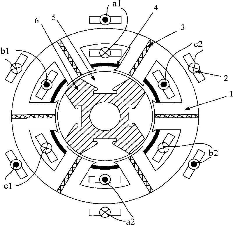
[0025] The mixed excitation block stator and rotor switched reluctance motor of the present invention can have a three-phase 6 / 4, four-phase 8 / 6 or three-phase 12 / 8 structure, etc., and its working principle is the same. When the center line of the fan-shaped rotor tooth block is aligned with the center line of the stator slot, it is defined as the rotor alignment position. At this time, the winding inductance is the largest; when the fan-shaped rotor tooth block center line is aligned with the centers of two adjacent stator teeth, it is defined as the rotor misalignment position. At this time, the winding Inductance is minimal.

[0026] The above three structures of the motor of the present invention are described in detail below in conjunction with the accompanying drawings:

[0027] The cross-sectional structure of the three-phase 6 / 4 structure motor of the present invention is as figure 1 As shown, it includes a U-shaped stator block 1, an excitation coil 2, a magnetic is...


PUM


Abstract

The invention discloses a composite excitation partitioned stator and rotor switched reluctance motor belonging to the field of switched reluctance motors. The motor can be in a three-phase 6/4, four-phase 8/6 or three-phase 12/8 structure and the like and comprises U-shaped stator blocks, excitation coils, magnet vanes, permanent magnets, segmental rotor tooth blocks and a non-magnetic conduction rotor metallic sheath, wherein the segmental rotor tooth blocks are embedded into the non-magnetic conduction rotor metallic sheath; one magnet vane is arranged between two adjacent U-shaped stator blocks; the permanent magnets are embedded between two stator tooth notches of each U-shaped stator block; the excitation coils are wound on the yokes of the U-shaped stator blocks; and the excitation field generated by each excitation coil wound on the yoke of each U-shaped stator block is in parallel connection with the permanent magnetic field generated by the permanent magnet embedded between two stator tooth notches of the U-shaped stator block. The motor of the invention has high torque, small wind resistance loss when the rotor operates at high speed, small end winding, strong fault tolerance and low production cost.

Description

technical field [0001] The invention relates to a motor, in particular to a hybrid excitation block stator and rotor switched reluctance motor, which belongs to the technical field of switched reluctance motors. Background technique [0002] The structure of the switched reluctance motor is simple and solid, low cost, reliable performance, flexible control, strong fault tolerance, and has the advantages of high temperature and high speed adaptability. However, the concave-convex rotor of the switched reluctance motor makes the wind resistance during high-speed operation very large, and the resistance during high-speed operation under oil cooling conditions is even greater. In order to reduce the wind (oil) resistance, the rotor injection method can be used, that is, the rotor is recessed. Partially filled with plastic, but this method is complex and costly to implement. The switched reluctance motor is a half-cycle output. How to further improve the motor efficiency and pow...

Claims


Application Information

Patent Timeline
IPC IPC(8): H02K29/00H02K1/17
Inventor 杨艳邓智泉陈小元许培林范娜连广坤
Owner NANJING UNIV OF AERONAUTICS & ASTRONAUTICS
Why Eureka
Try Eureka