Wavelength-encoding optical time domain reflection test device and measurement method thereof

An optical time domain reflectometry and testing device technology, which is used in measurement devices, optical instrument testing, and machine/structural component testing. Noise, the effect of improving sensitivity

Active Publication Date: 2010-06-30
INST OF SEMICONDUCTORS - CHINESE ACAD OF SCI
View PDF1 Cites 33 Cited by
  • Summary
  • Abstract
  • Description
  • Claims
  • Application Information

AI Technical Summary

Problems solved by technology

[0005] In order to solve the above problems, the main purpose of the present invention is to provide a high resolution, large dynamic range, simple structure optical time

Method used


Image

  • Wavelength-encoding optical time domain reflection test device and measurement method thereof
  • Wavelength-encoding optical time domain reflection test device and measurement method thereof
  • Wavelength-encoding optical time domain reflection test device and measurement method thereof

Examples


Embodiment 1

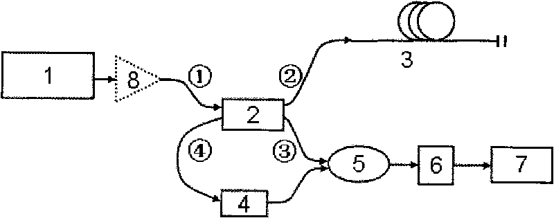
[0040] See figure 1 , The wavelength-coded optical time-domain reflection test device of the present invention is mainly composed of an optical wavelength-coded generator, an optical fiber splitting device, a polarization controller, a photodetector and a beat signal detection device.

[0041] The optical wavelength code generator is composed of a coded signal generator and a tunable light source; the coded signal generator is a waveform generator or a programmable pulse source, and the period and pulse of the output coded signal can be arbitrarily controlled by manual or computer settings Parameters such as width, pulse amplitude and pulse timing; the tunable light source is a distributed Bragg reflection (DBR) laser or other types of tunable lasers. The tunable light source can achieve fast wavelength tuning, that is, in the code signal generator Under the control of the output code signal, the corresponding coded light pulse signal can be generated. In the distributed Bragg r...

Embodiment 2

[0044] figure 1 It also shows the measurement method used for the wavelength-coded optical time domain reflectance test device. The method is to combine two different wavelengths (λ 1 , Λ 2 ) The coded light pulse signal composed of light is divided into the detection light signal and the reference light signal, such as Figure 4 As shown in (a), after the probe optical signal enters the optical fiber link 3 to be tested, it will produce a reflected optical signal when it encounters a fiber break or damage point, such as Figure 4 As shown in (b), the reflected light signal and the reference light signal enter the photodetector 6 for beat frequency, and the beat frequency signal enters the beat frequency signal detection device 7 for observation and recording. By adjusting the wavelength of the encoded optical pulse signal to λ 1 And λ 2 The time interval T of the two light pulses 1 , And observe and record the frequency spectrum of the corresponding beat frequency signal. When ...


PUM


Abstract

The invention discloses a wavelength-encoding optical time domain reflection test device and a measurement method thereof. The device comprises an optical wavelength encoding generator, an optical fiber splitting device, a polarization controller, an optical fiber coupler, a photoelectric detector and a beat frequency signal detection device; wherein an encoding optical pulse signal generated from the optical wavelength encoding generator is input from a first port of the optical fiber splitting device and divided into a detection light signal and a reference light signal which are respectively output from a second port and a third port of the optical fiber splitting device; the detection light source enters into an optical fiber link to be tested, and a reflected light signal generated after meeting breakpoints or damages of the optical fiber link to be tested returns to the optical fiber splitting device from the second port and is output from a fourth port; the reflected light signal passes through the polarization controller, then passes through the optical fiber coupler together with the reference light signal and enters into the photoelectric detector to carry out frequency beating, and a beat-frequency low-frequency signal enters into the beat-frequency signal detection device and is then observed and recorded. The invention solves the problems that the OTDR resolution ratio and the dynamic range of the traditional device can not be simultaneously improved.

Description

Technical field [0001] The invention relates to the technical field of optical fiber link testing, in particular to a wavelength-coded optical time domain reflection testing device and a measurement method thereof. Background technique [0002] Optical Time-Domain Reflectometer (OTDR) is abbreviated as OTDR. It is a test instrument based on backscattered or reflected light signals. It is a typical optical time-domain reflectometer. OTDR generally includes light source, optical fiber coupler or optical circulator, optical detector, signal processing and display, etc. Traditional OTDR uses pulsed laser as the light source. The pulsed laser emits light pulses to the optical fiber link to be tested. The power and transmission time obtain parameters such as loss characteristics and reflection distance. This instrument can conveniently perform non-destructive detection of optical fiber links or systems, and can continuously display the relative position changes and fault points of the...

Claims


Application Information

Patent Timeline
IPC IPC(8): H04B10/08H04B10/12G01M11/00H04B10/071H04B10/25
Inventor 祝宁华刘宇谢亮王欣袁海庆
Owner INST OF SEMICONDUCTORS - CHINESE ACAD OF SCI
Why Eureka
Try Eureka