Differential detecting capacitance type touch control method and system

A capacitive touch and detection circuit technology, applied in the direction of electrical digital data processing, input/output process of data processing, instruments, etc., can solve problems such as jitter, small change of mutual inductance capacitance Cm, and reduced signal-to-noise ratio , to achieve the effect of reducing common noise, improving accuracy, and improving signal-to-noise ratio

Active Publication Date: 2010-07-07
ORISE TECH CO LTD
View PDF0 Cites 25 Cited by
  • Summary
  • Abstract
  • Description
  • Claims
  • Application Information

AI Technical Summary

Problems solved by technology

[0009] When a conductor or a finger approaches or touches the panel, the variation of the mutual inductance capacitance Cm is very small, so it is easily affected by external common noise. After the common noise is amplified by the programmable gain amplifier 120, the overall system performance is reduced. Signal to Noise Ratio (SNR), so the signal D(1)-K~D(n)-K output by the offset device 140 will have a jitter phenomenon due to more noise, which will cause the coordinate judging device The coordinates of the contact points generated by 160 are unstable, or even incorrect

Method used


Image

  • Differential detecting capacitance type touch control method and system
  • Differential detecting capacitance type touch control method and system
  • Differential detecting capacitance type touch control method and system

Examples


Embodiment Construction

[0027] In order to make the object, technical solution and advantages of the present invention clearer, the solutions of the present invention will be further described in detail below with reference to the accompanying drawings and examples.

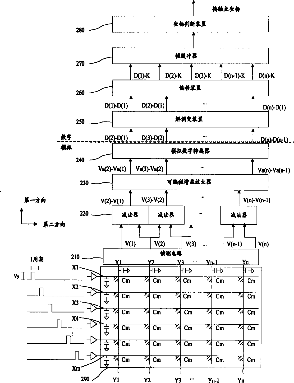
[0028] figure 2 It is a structural diagram of a system for differentially detecting capacitive touch in the present invention. The demodulation system includes: a detection circuit 210, a set of subtractors 220, a set of programmable gain amplifiers 230, and an analog-to-digital conversion device 240, a demodulator 250, an offset device 260, a frame buffer 270, and a coordinate judging device 280.

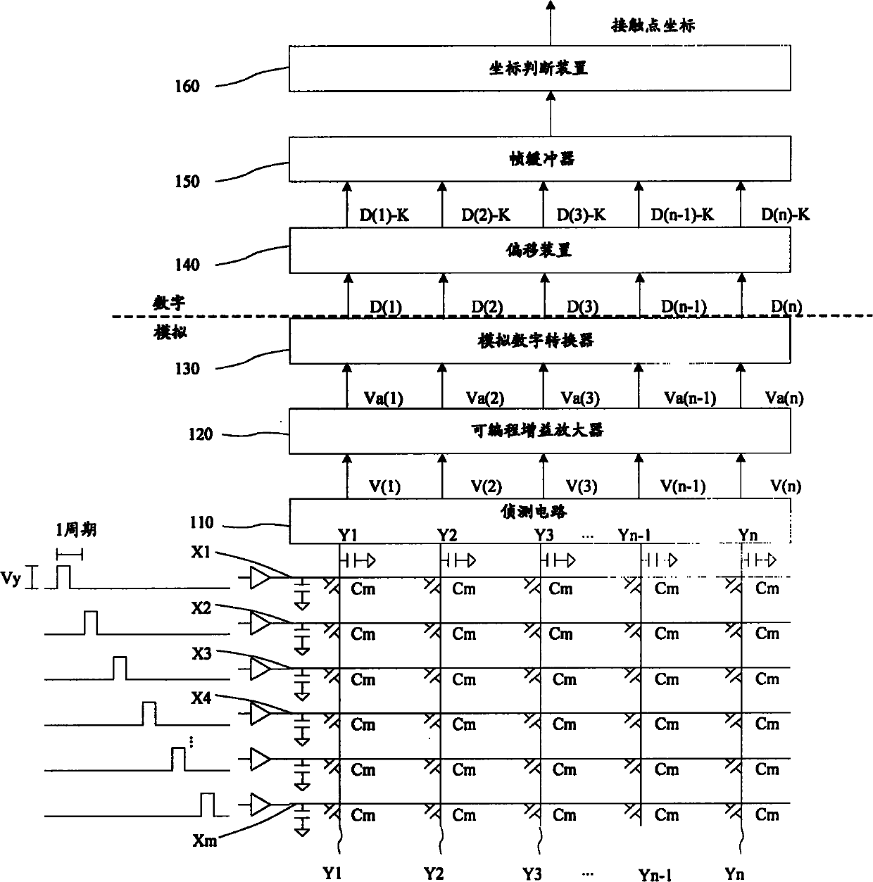
[0029] The detection circuit 210 has n input terminals for detecting the sensing capacitance of n wires of the capacitive touch panel 290 , and then generating corresponding n sensing signals.

[0030] In the present invention, the induction signal can be an induction voltage or an induction current. For the convenience of description, in ...


PUM


Abstract

The invention provides a differential detecting capacitance type touch control system which comprises a detecting circuit, a group of subtracters, a group of programmable gain amplifiers, an analog-digital converter and a demodulating device, wherein the detecting circuit is used for detecting the inducing capacitance of n leads of a capacitance type touch control panel and generating n corresponding induction signals; the subtracters are used for carrying out pairwise subtraction on the n induction signals to generate n-1 differential signals; the programmable gain amplifiers are used for amplifying the n-1 differential signals to generate n-1 amplified differential signals; the analog-digital converter is used for converting the n-1 amplified differential signals into n-1 digital differential signals; and the demodulating device is used for demodulating the n-1 digital differential signals into n-1 digital signals. Meanwhile, the invention also provides a differential detecting capacitance type touch control method. The method and the device can prevent common noise from being amplified by the programmable gain amplifiers and improve the judging accuracy of contact point coordinates.

Description

technical field [0001] The invention relates to the technical field of touch panels, in particular to a method and system for differentially detecting capacitive touch. Background technique [0002] Most modern consumer electronic devices are equipped with touch pads as one of their input devices. In order to meet the needs of lightness, thinness, shortness, and smallness, the touchpad is often integrated with the panel to form a touch panel, which is convenient for users to input. According to different sensing principles, touch panels can be divided into four types: resistive, capacitive, acoustic, and optical. [0003] The technical principle of the touch panel is that when a finger or other medium touches the touch panel, it detects voltage, current, sound waves or infrared rays according to different sensing methods, and then measures the coordinates of the touch point. For example, the resistive type uses the potential difference between the upper and lower electrode...

Claims


Application Information

Patent Timeline
Patent Type & Authority Applications(China)
IPC IPC(8): G06F3/044
Inventor 黄彦霖王信濠
Owner ORISE TECH CO LTD
Why Eureka
Try Eureka