Gas supply device

A technology for gas supply and gas treatment, which is applied in the fields of electrical components, gaseous chemical plating, semiconductor/solid-state device manufacturing, etc. The effect of a small diffusion space

Active Publication Date: 2010-07-07
TOKYO ELECTRON LTD
View PDF3 Cites 18 Cited by
  • Summary
  • Abstract
  • Description
  • Claims
  • Application Information

AI Technical Summary

Problems solved by technology

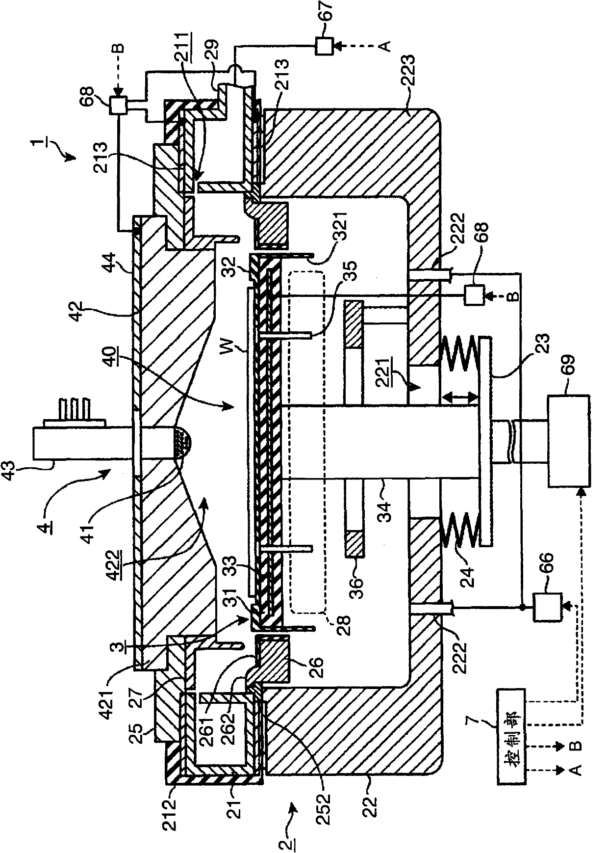
However, in the case of such an apparatus, there is the following problem: the gas flow of the discharged processing gas collides with the side wall of the processing container 2 to generate a vortex, and gas stagnation is easily formed to prevent the complete discharge of the processing gas.

Method used


Image

  • Gas supply device
  • Gas supply device
  • Gas supply device

Examples


Embodiment 1-1

[0136] like Figure 18 As shown, in the film forming apparatus 1 of the above-mentioned embodiment, the space through which the gas flows (the circulation space 430, the inside of the gas supply nozzle 41, and the diffusion space 40 (processing ambient gas)) is created on the basis of the central position of the space. A model space that is divided into four in the circumferential direction. Then, a simulation was performed in which the concentration of the processing gas in the model space was increased from 0 vol% to 4.0 vol% by supplying the processing gas.

[0137] At this time, the concentration distribution of the processing gas at the time of 0.01 second after the start of the supply of the processing gas was obtained. When the processing gas is supplied, in order to prevent back diffusion of the gas, a reverse gas is supplied simultaneously with the processing gas. exist Figure 18 In , the processing gas is supplied from the position indicated by the solid line arr...

Embodiment 1-2

[0144] Under the same conditions as in (Example 1-1), the concentration distribution of the processing gas at the time of 0.1 second after the start of supply of the processing gas was obtained.

Embodiment 2-1

[0146] A simulation was performed in which a purge gas was supplied to reduce the concentration of the processing gas from 4.0 vol% to 0 vol% in the phantom space after the processing gas was supplied under the conditions of (Example 1-1) and (Example 1-2).

[0147] The processing gas concentration distribution at the time of 0.01 second elapsed from the start of the supply of the processing gas was obtained. Figure 18 The solid line (hereinafter referred to as the processing gas pipeline) and the dotted line (hereinafter referred to as the reverse filling gas pipeline) are supplied with argon as a purge gas.

[0148] Process gas pipeline supply

[0149] Argon 500mL / min(sccm)

[0150] Reverse fill gas line supply

[0151] Argon 1500mL / min(sccm)


PUM


Abstract

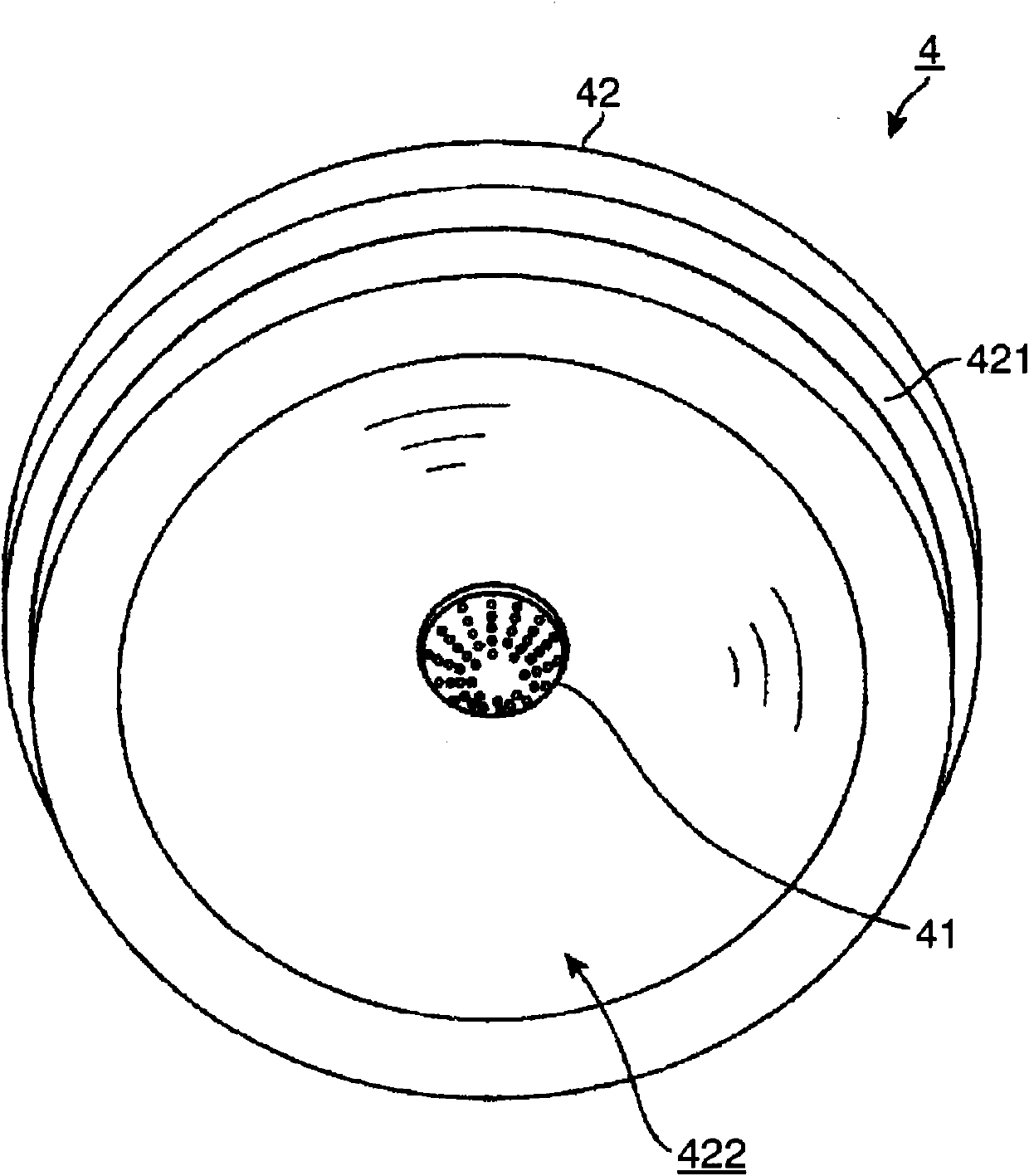
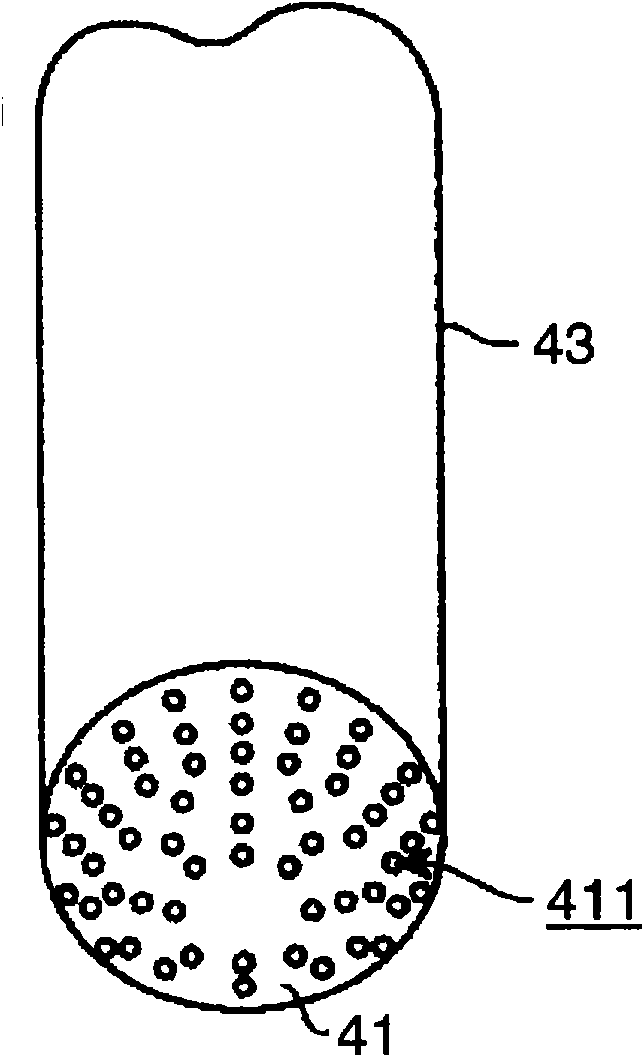
A gas supply device disposed opposite to a substrate mounted on a stage in a processing container and supplying a process gas for processing the substrate comprises a top plate member having a recess formed to spread gradually toward the stage in order to constitute a gas diffusion space at a position facing the substrate on the stage, and a gas supply nozzle projecting into the recess from the top thereof and having a plurality of gas supply holes along the circumferential direction of the recess.

Description

technical field [0001] The present invention relates to a technique of supplying a processing gas for processing a substrate in a processing container into a processing container. Background technique [0002] In a semiconductor manufacturing apparatus, a gas supply device and a mounting table are opposed to each other in a processing container, and a processing gas is supplied from the gas supply device to a substrate mounted on the mounting table, for example, a semiconductor wafer (hereinafter simply referred to as a wafer) to process the substrate. Devices, such as film forming devices and etching devices, etc. [0003] Among them, as a film forming device, there is a thermal CVD device that heats a processing gas to cause a reaction, and the like. In addition, ALD (Atomic Layer Deposition: Atomic Layer Deposition) or MLD (Molecular Layer Deposition: Molecular Layer Deposition) and other processes are known, that is, the supply of various processing gases is divided int...

Claims


Application Information

Patent Timeline
IPC IPC(8): H01L21/316C23C16/455H01L21/31
CPCC23C16/45508C23C16/45563C23C16/45531C23C16/45544C23C16/45582C23C16/409C23C16/45559
Inventor 津田荣之辅
Owner TOKYO ELECTRON LTD
Why Eureka
Try Eureka