Chip fixing glue for LED (Light Emitting Diode)

A technology of solid crystal glue and silica gel, which is applied in the direction of adhesives, adhesive additives, electrical components, etc., can solve the problems that are difficult to meet the reliability requirements of packaged LEDs, and achieve the advantages of LED chip bonding, low fluidity, and low ionization. The effect of content

Inactive Publication Date: 2010-07-14
ANHUI ZERUN OPTOELECTRONICS
View PDF0 Cites 7 Cited by
  • Summary
  • Abstract
  • Description
  • Claims
  • Application Information

AI Technical Summary

Problems solved by technology

However, the performance of LED die-bonding adhesives currently on the market cannot meet the reliability requirements of packaged LEDs.

Method used


Image

  • Chip fixing glue for LED (Light Emitting Diode)
  • Chip fixing glue for LED (Light Emitting Diode)

Examples


Embodiment Construction

[0039] In order to further describe the present invention, the LED die-bonding adhesive of the present invention will be further described below in conjunction with examples.

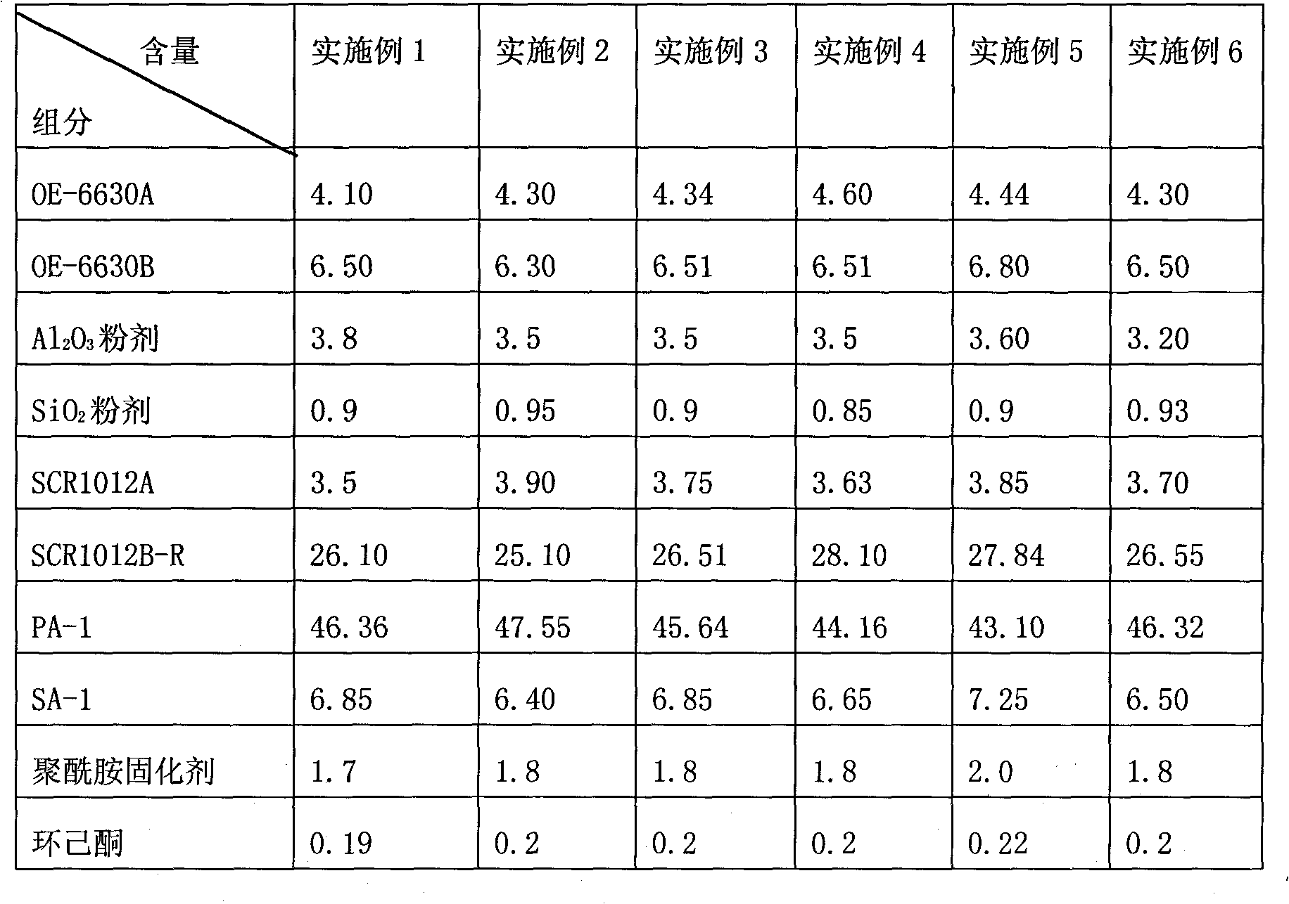
[0040] According to the components and contents (% by weight) listed in Table 1, the LED die-bonding glue was prepared. All components are commercially available.

[0041] Table 1 Components and content of LED die-bonding glue (100% by weight)

[0042]

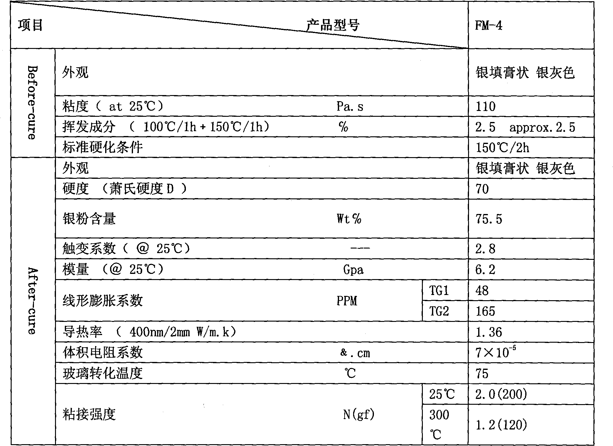
[0043] The properties of the LED die-bonding adhesive in Example 3 are shown in Table 2.

[0044] Table 2 Product performance of LED die-bonding adhesive

[0045]

[0046] (Note: Before-cure: before baking; After-cure: after baking)

[0047] After testing, the properties of the LED die-bonding adhesives obtained in Examples 1, 2, 4, 5, and 6 are basically the same as those in Table 2.

[0048] The method of use is as follows:

[0049] A. Take out a certain amount of LED crystal-bonding glue from the freezer and put it in an anti-static bag, w...


PUM

PropertyMeasurementUnit
viscosityaaaaaaaaaa
viscosityaaaaaaaaaa
viscosityaaaaaaaaaa

Abstract

The invention discloses a chip fixing glue for LEDs (Light Emitting Diodes), which is prepared form the following components by percentage content (total weight of 100percent): 4.10% -4.60%of OE-6630A (silicone main agent); 6.30% -6.80% of OE-6630B (silicone curing agent); 3.20% -3.80% of aluminum oxide powder (Al2O3); 0.85% -0.95% of silica powder (SiO2); 3.50% -3.90% of SCR1012A (silicone main agent); 25.10%-28.10% of SCR1012B-R (silicone curing agent); 43.10% -47.55% of PA-1(flake silver powder); 6.40% -7.25% of SA-1 (granular silver powder); 1.7% -2.0% of polyamide curing agent; and 0.19% -0.22% of cyclohexanone. The invention has the advantages of high positioning accuracy, high-temperature and high heat resistance, high heat conductivity, high light transmission, high refrangibility, favorable confidence degree, convenient and quick use and low price and can be widely used for the bonding of chips of LED components, such as SMD (surface mount device), PLCC (plastic leaded chip carrier), LAMP, and DISPLAY and the like.

Description

technical field [0001] The invention relates to a bonding material for LEDs, in particular to an LED crystal-bonding adhesive, which can be widely used in surface-mounted light-emitting diodes (SMDs), PPA plastic-cased surface-mounted light-emitting diodes (PLCCs), direct Bonding of chips (CHIP) of LED components such as plug-in light-emitting diodes (LAMP) and digital tubes (DISPLAY). Background technique [0002] The global energy shortage and environmental pollution are particularly prominent in China, where the economy is developing rapidly. Energy conservation and environmental protection are issues that need to be solved urgently for China to achieve sustainable social and economic development. The annual lighting power consumption accounts for about 12%-15% of the total power consumption. As a large energy consumer, it is necessary to find a new generation of energy-saving and environmentally friendly light sources that can replace traditional light sources as soon as...

Claims


Application Information

Patent Timeline
Patent Type & Authority Applications(China)
IPC IPC(8): C09J183/00C09J11/04C09J11/08H01L33/56
Inventor 孟杰陈和生包书林
Owner ANHUI ZERUN OPTOELECTRONICS
Why Eureka
Try Eureka