Dielectric-capacitance testing method of deformation degree of transformer winding

A transformer coil, deformation degree technology, applied in the direction of electric/magnetic solid deformation measurement, instruments, measuring devices, etc., can solve the problems of inability to accurately determine the coil deformation position, field wiring interference, etc., to ensure normal and safe operation and improve work. The effect of quality and efficiency

Inactive Publication Date: 2010-07-14
HEBEI ELECTRIC POWER RES INST
View PDF0 Cites 15 Cited by
  • Summary
  • Abstract
  • Description
  • Claims
  • Application Information

AI Technical Summary

Problems solved by technology

These two methods are susceptible to field wiring interference and cannot accurately determine the coil deformation position when judging the degree of deformation of the transformer coil, so there are certain limitations.

Method used


Image

  • Dielectric-capacitance testing method of deformation degree of transformer winding
  • Dielectric-capacitance testing method of deformation degree of transformer winding
  • Dielectric-capacitance testing method of deformation degree of transformer winding

Examples


Embodiment 1

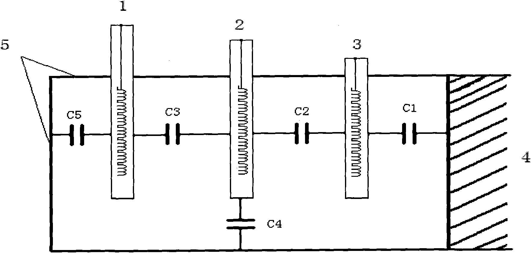
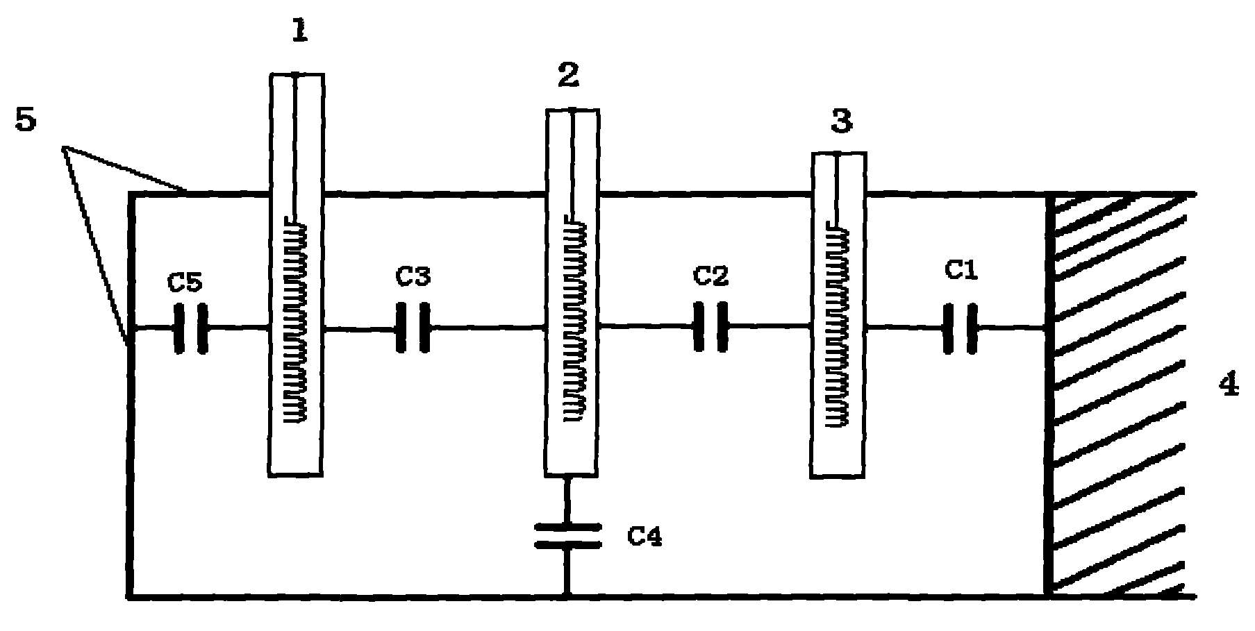
[0028] Embodiment 1: overall introduction method

[0029] Test wiring: The measuring instrument adopts the high-voltage dielectric loss meter based on the principle of Xilin bridge. And ground dielectric loss and capacitance measurement. Through the test data of the five dielectric losses and capacitances of the high, medium and low windings of the transformer, the capacitance of the low voltage winding to ground; the capacitance between the medium and low voltage windings; the capacitance between the high and medium voltage windings; The capacitance of the voltage winding to the ground; the capacitance and dielectric loss of the high voltage winding to the ground. Through these five dielectric loss and capacitance changes from the factory value, the degree of coil deformation of the voltage level of the transformer coil can be judged. The capacitance and dielectric loss of each part of the test wiring and the tested transformer are shown in Table 1:

[0030] Table 1 Test w...

Embodiment 2

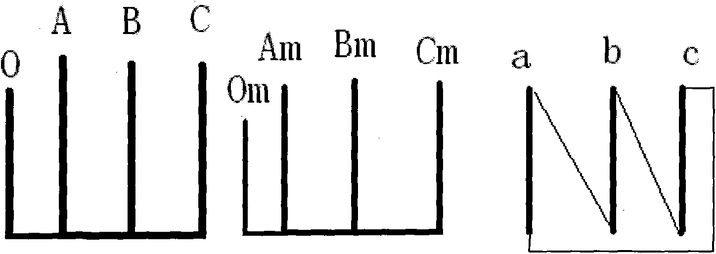
[0040] Embodiment 2: interphase capacity method

[0041] In order to accurately detect the degree of deformation of which phase coil of the transformer, the phase-to-phase dielectric loss and capacitance of the winding are tested separately, that is, the high-voltage windings A, B, and C are respectively measured relative to the medium-voltage windings Am, Bm, and Cm phases, and the medium-voltage The windings Am, Bm, and Cm are relatively low-voltage windings a, b, and c-phase, and the dielectric loss and capacitance of the low-voltage winding to the iron core. Most of the 110-220kV transformers operating in the domestic power grid are connected at points Yn, yn0, and d11. The voltage levels of high-voltage windings are 110kV and 220kV, the voltage levels of medium-voltage windings are 35kV and 110kV, and the voltage levels of low-voltage windings are 10kV and 35kV. two kinds. The low-voltage winding connection method is to connect the 11-point connection method inside the t...


PUM


Abstract

The invention provides a dielectric-capacitance testing method of the deformation degree of a transformer winding, belonging to the technical field of test of electric appliance components. The deformation degree of the transformer winding is judged by testing the variation of the dielectric loss and capacitance of the transformer winding. The invention has the advantages that shortage of the prior art is overcome, the deformation degree of the transformer winding is judged by testing the variation of the dielectric loss and capacitance of the transformer winding, the deformation degree of the transformer winding can be accurately judged by an overall dielectric-capacitance method or an interphase dielectric-capacitance method or by complementation and confirmation therebetween so that the repair the operating state of the transformer can be timely and accurately monitored, normal and safe operation of the transformer is ensured, and the working quality and the efficiency of the transformer are improved. The method is particularly suitable for testing the deformation degree of the transformer winding with the voltage of 110kV or above.

Description

technical field [0001] The invention relates to the technical field of testing electrical structural components, in particular to a capacitance-inducing test method for transformer coil deformation degree used in power systems to judge high-voltage levels. Background technique [0002] At present, the test methods for diagnosing the deformation degree of transformer coils in domestic power systems mainly include the frequency response method and the low-voltage short-circuit impedance method. These two methods are susceptible to field wiring interference and cannot accurately determine the coil deformation position when judging the deformation degree of the transformer coil, so they have certain limitations. [0003] In order to accurately judge the degree of deformation of the transformer coil, a new test method - capacitance method is adopted. The dielectric capacitance method is a new method for judging the deformation degree of the transformer winding by measuring the c...

Claims


Application Information

Patent Timeline
Patent Type & Authority Applications(China)
IPC IPC(8): G01B7/16G01R27/26
Inventor 陈志勇高骏刘宏亮杜大全
Owner HEBEI ELECTRIC POWER RES INST
Why Eureka
Try Eureka