High-gain and high-power antenna based on materials with low refractive index

A low-refractive-index, high-gain technology, applied in the direction of antennas, electrical components, etc., can solve the problems of large return loss and low power capacity of directional antennas, and achieve the effect of improving directivity

Inactive Publication Date: 2010-07-14
INST OF OPTICS & ELECTRONICS - CHINESE ACAD OF SCI
View PDF0 Cites 16 Cited by
  • Summary
  • Abstract
  • Description
  • Claims
  • Application Information

AI Technical Summary

Problems solved by technology

[0005] The technical problem to be solved by the present invention is to provide a high-gain, high-power antenna based on low-refractive-index materials in view of the shortcomings of low power capacity and large return loss of existing directional antennas based on sub-wavelength low-refractive index artificial structural materials , the antenna uses a waveguide instead of the previous patch and monopole as the antenna feed, and uses a double-layer all-metal copper mesh structure to construct an equivalent low-refractive index material, which improves the power of the antenna while ensuring high antenna gain, and reduces Antenna VSWR

Method used


Image

  • High-gain and high-power antenna based on materials with low refractive index
  • High-gain and high-power antenna based on materials with low refractive index
  • High-gain and high-power antenna based on materials with low refractive index

Examples


Embodiment 1

[0046] (1) The working frequency of the antenna is selected as 15 GHz according to user requirements. The selected waveguide is a standard BJ140 rectangular waveguide, the length of the wide side is 15.8mm, and the length of the narrow side is 7.9mm.

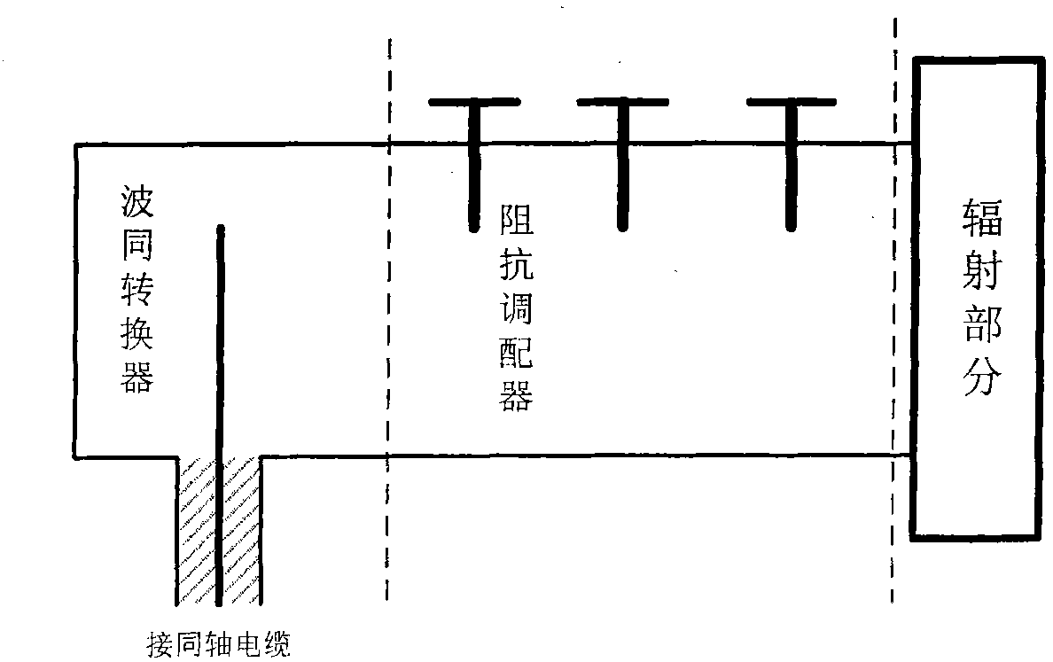
[0047] (2) The waveguide-coaxial converter is a door knob waveguide-coaxial converter. The connector is a standard N-type connector, and the surface of the streamlined inner conductor of the converter is silver-plated. The VSWR of this type of connector is wider than that of small bandwidth and supports larger power.

[0048] (3) The impedance adjuster uses a three-screw impedance adjuster, which has a large adjustment range, is easy to integrate into the waveguide, and has low cost. The final radiation part of the antenna is like figure 2 As shown, integrating the converter and impedance adjuster on the waveguide reduces the volume of the device.

[0049] (4) The directivity coefficient of a given antenna is D=25dB, and the apertur...


PUM


Abstract

The invention provides a high-gain and high-power antenna based on materials with low refractive index. The method for designing the antenna comprises the following steps: (1) determining the working frequency f of the antenna; (2) selecting the corresponding waveguide, waveguide-coaxial transformer, transformer connector and impedance tuner according to the working frequency f thereof, so as to change the mode of the electromagnetic wave and match the impedance; (3) selecting a proper aperture A according to the geometric dimension limit and the directivity D of the antenna; (4) determining the geometric dimensions of the sub-wavelength artificial-structure material with low refractive index, wherein the material has the structure of a double-layer metal copper mesh, no dielectric medium is added between the two layers of the copper mesh, and the geometric parameters of the structure are mainly the period a of the copper mesh, the side length b of a hollow cavity, the thickness t of the copper mesh, and the distance Dis_layer between the two layers of the copper mesh; and (5) selecting the proper distance Distance between the material and the ground metal plate through simulation, and acquiring the maximum directivity and minimum standing-wave ratio (SWR) by adjusting the impedance tuner according to the tests. The invention can simultaneously guarantee the high gain of the antenna and increase the power of the antenna, and reduces the SWR of the antenna.

Description

Technical field: [0001] The invention relates to an antenna, in particular to a directional antenna with high gain and high power capacity based on a low refractive index artificial structure material. Background technique [0002] Directional antennas, as the name suggests, are antennas with one or more directions with the greatest radiation and reception capabilities. Directional antennas have concentrated energy, and the directional coefficient and gain are many times higher than that of omnidirectional antennas. At the same time, they have strong anti-interference ability. They are usually used in point-to-point communications at long distances, such as communications between satellites and ground base stations. The more mature directional antennas currently developed include helical spotlight antennas, Yagi-Uda antennas, horn antennas and patch antennas also have certain directional properties. These antennas have their own advantages and disadvantages, and are widely used ...

Claims


Application Information

Patent Timeline
Patent Type & Authority Applications(China)
IPC IPC(8): H01Q13/00H01Q13/08H01Q15/02
Inventor 董小春史浩飞袁桂山史立芳邓启凌杜春雷
Owner INST OF OPTICS & ELECTRONICS - CHINESE ACAD OF SCI
Why Eureka
Try Eureka