Power converter
A power conversion device and power conversion technology, which is applied in the modification of power consumption devices, control devices, power electronics, etc., can solve problems such as semiconductor loss, and achieve the effect of reducing and suppressing thermal effects.
- Summary
- Abstract
- Description
- Claims
- Application Information
AI Technical Summary
Problems solved by technology
Method used
Image

Examples
Embodiment 2
[0083] Below, refer to Figure 9 , and describe the second embodiment of the present invention.
[0084] This embodiment is an improved example of the first embodiment, and the same components are assigned the same symbols, and will not be described again.
[0085] The difference between this embodiment and the first embodiment is that a third cooling cavity surrounded by the upper casing 10 and the second upper casing 19 is formed on the upper part of the cooling cavity containing the semiconductor modules 20 and 30, and the drive circuit A substrate 97 including a substrate, a control circuit substrate, and a connector substrate is accommodated therein.
[0086] The wiring sheets of the semiconductor modules 20 and 30 and the substrate 97 are electrically connected by a wiring member 98 .
[0087] The capacitor case of the capacitor 50 is omitted and replaced by pi-shaped legs of the second base 12 . Therefore, the π-shaped legs of the second base 12 are formed to extend ...
Embodiment 3
[0091] Below, refer to Figure 10 , and describe the third embodiment of the present invention.
[0092] This embodiment is an improved example of the first embodiment, and the same components are assigned the same symbols, and will not be described again.
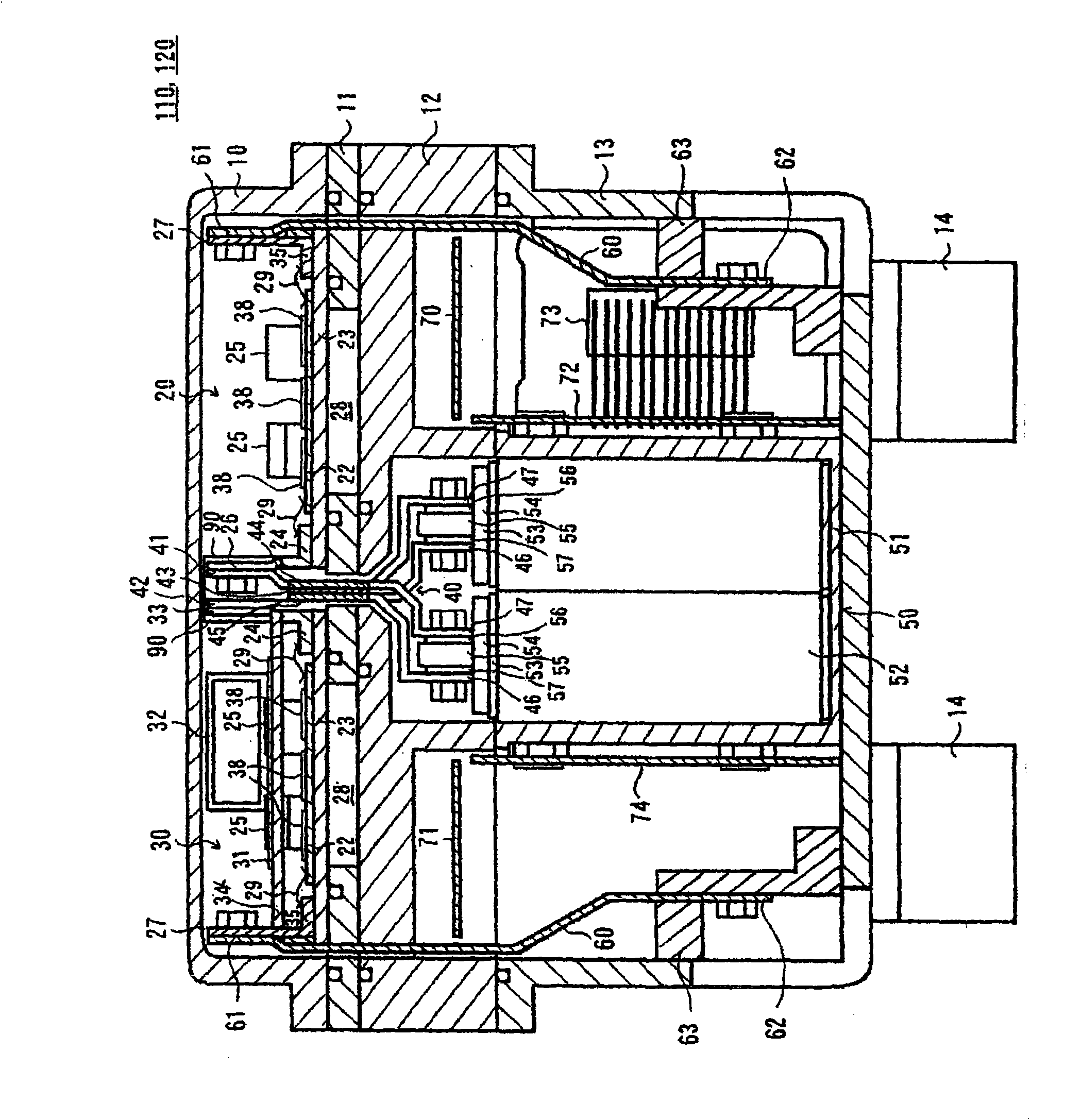
[0093] The difference between the present embodiment and the first embodiment is that the drive circuit boards 70, 71, the AC bus bar 60, and the terminal bracket 63 are housed together in the cooling chamber for housing the semiconductor modules 20, 30.
[0094]In addition, below the cooling chamber for storing the semiconductor modules 20 and 30 , a second cooling chamber is formed by the second base 12 , and further, two third cooling chambers are formed by the second base 12 therebelow. The capacitor 50 is housed in the second cooling chamber; the control circuit board 74 is housed in one of the third cooling chambers; and the connector board 72 is housed in the other third cooling chamber. The capacitor 50 is horizo...
Embodiment 4
[0098] Below, refer to Figure 11 and Figure 12 , and describe the fourth embodiment of the present invention.
[0099] This embodiment is an improved example of the first embodiment, and the same components are assigned the same symbols, and will not be described again.
[0100] The difference between this embodiment and the first embodiment is that the rear wheels 201 are also driven by the motor generator 160 . Therefore, in this embodiment, a set of inverter devices 150 is provided. The power of the motor generator 160 is decelerated by the speed reducer 204 , then transmitted to the rear wheel differential gear 203 , and then transmitted to the rear wheel axle 202 by the rear wheel differential gear 203 . That is, in this embodiment, a four-wheel drive type hybrid vehicle is configured. Inverter device 150 is connected to battery 106 . When motor generator 160 is used as a motor, power is supplied from battery 106 to inverter device 150 ; when motor generator 160 is...
PUM
 Abstract
Description
Claims
Application Information
 - R&D
- Intellectual Property
- Life Sciences
- Materials
- Tech Scout
- Unparalleled Data Quality
- Higher Quality Content
- 60% Fewer Hallucinations
Browse by: Latest US Patents, China's latest patents, Technical Efficacy Thesaurus, Application Domain, Technology Topic, Popular Technical Reports.
© 2025 PatSnap. All rights reserved.Legal|Privacy policy|Modern Slavery Act Transparency Statement|Sitemap|About US| Contact US: help@patsnap.com