Logarithmic amplifier

A logarithmic amplifier, a technology of amplifiers, applied in amplifiers, improving amplifiers to improve efficiency, amplifiers with semiconductor devices/discharge tubes, etc. The effect of eliminating DC offset, improving the ability to resist PVT deviation, and ensuring stability

Active Publication Date: 2010-07-14
TSINGHUA UNIV
View PDF0 Cites 2 Cited by
  • Summary
  • Abstract
  • Description
  • Claims
  • Application Information

AI Technical Summary

Problems solved by technology

[0007] The technical problem to be solved by the present invention is to provide a logarithmic amplifier to solve the defects of existing logarithmic amplifiers such as large power consumption and low ability to resist PVT deviation

Method used


Image

  • Logarithmic amplifier
  • Logarithmic amplifier
  • Logarithmic amplifier

Examples


Embodiment 1

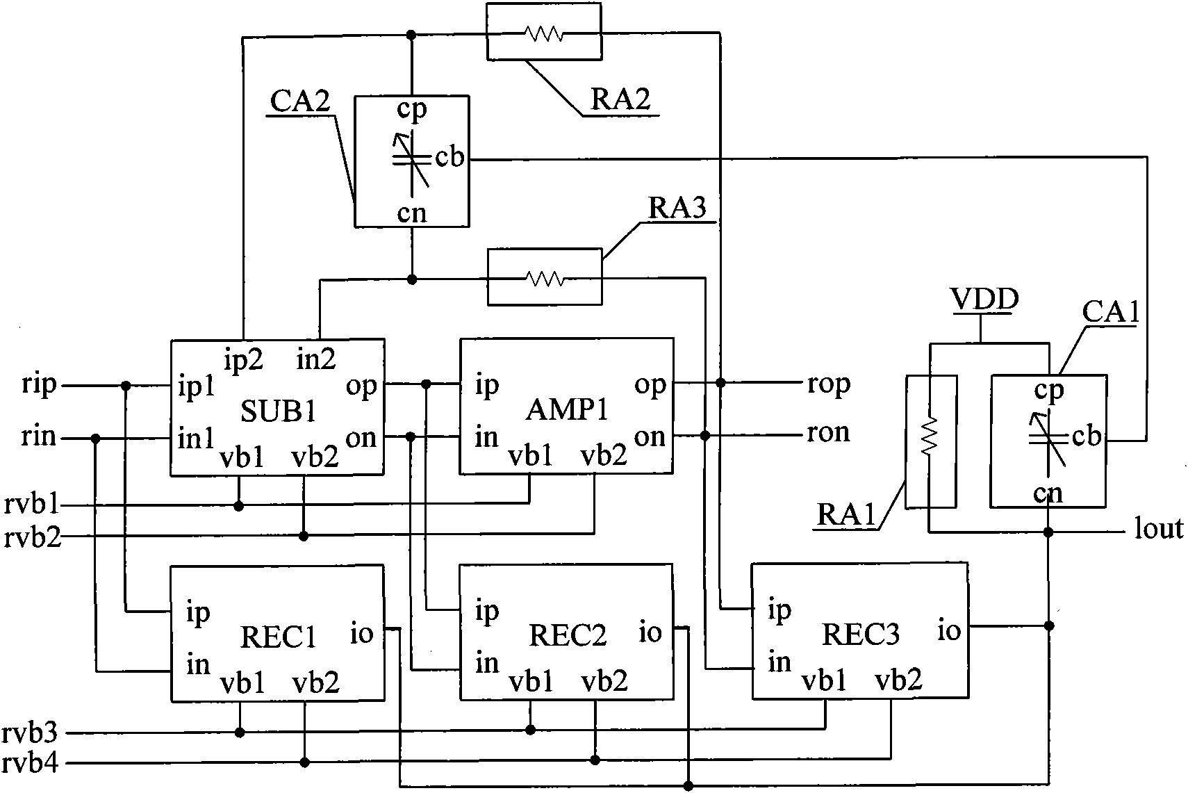
[0046] Such as figure 1 Shown is a schematic diagram of the circuit structure of Embodiment 1 of the logarithmic amplifier of the present invention. The logarithmic amplifier of the present invention comprises: subtractor SUB1, amplifier AMP1, rectifier REC1, REC2, REC3, and the output low-pass filter that is made up of variable capacitance array CA1 and resistance array RA1, by variable capacitance array CA2, resistance array RA2 and the low-pass filter of the feedback network composed of resistor array RA3.

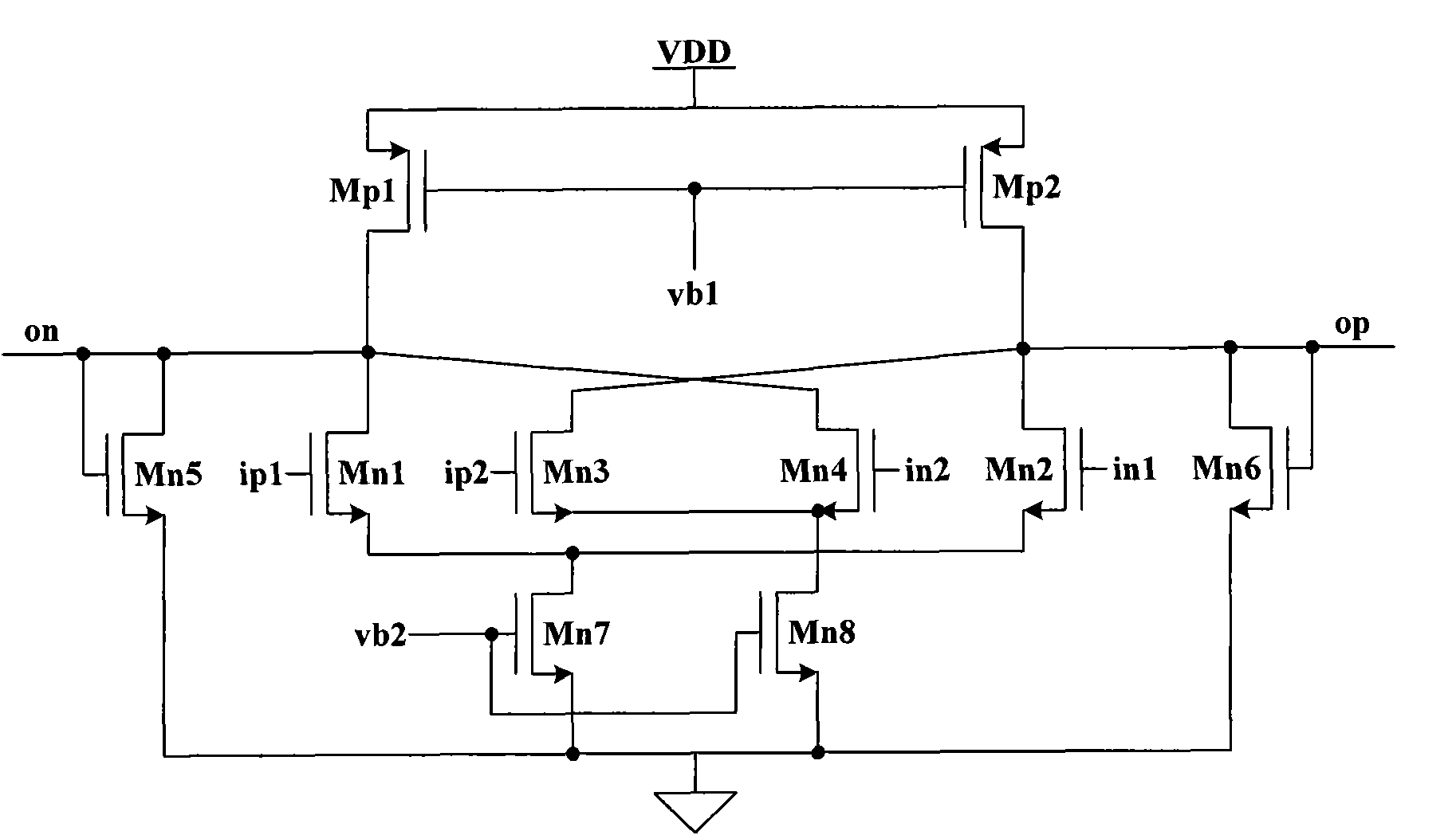
[0047] Wherein the number of subtractors is at least one, and this embodiment takes one subtractor as an example, and it can also be multiple; the number of amplifiers is at least one, and this embodiment takes one amplifier as an example; the number of rectifiers is at least three, and this implementation Example Take three rectifiers as an example. The subtractor and the amplifier in this embodiment adopt a folded subtractor and amplifier; the rectifier adopts a rec...

Embodiment 2

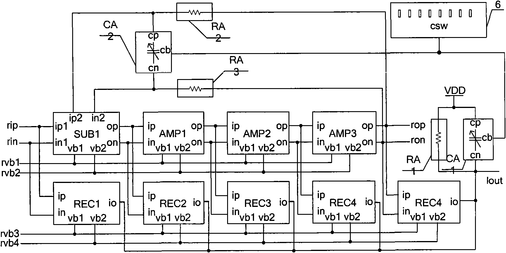
[0055] Such as figure 2 As shown, it is a schematic diagram of the circuit structure of Embodiment 2 of the logarithmic amplifier of the present invention; the difference between this embodiment and Embodiment 1 is that this embodiment also includes: amplifiers AMP2 and AMP3, rectifiers REC4 and REC5, and a time constant correction circuit 9 .

[0056] Among them, the differential input terminals ip and in of AMP2 are respectively connected with the differential output terminals op and on of AMP1; the differential input terminals ip and in of AMP3 are respectively connected with the differential output terminals op and on of AMP2; the differential output terminals op of AMP3 , on are respectively connected to the differential output terminals rop and ron of the logarithmic amplifier; the first bias voltage input terminal vb1 of AMP1, the first bias voltage input terminal vb1 of AMP2, the first bias voltage input terminal vb1 of AMP3 and After the first bias voltage input ter...


PUM


Abstract

The invention discloses a logarithmic amplifier which comprises a subtracter in a folding structure, at least one amplifier in a folding structure, at least three rectifiers in a current subtracter structure, two variable capacitor arrays and three resistor arrays. The logarithmic amplifier provided by the invention has lower power and stronger anti-PVT bias capability, automatically corrects a resistance-capacitance time constant by controlling a time constant correction circuit, ensures the response speed and the ripple characteristics of an output signal in case of PVT bias, ensures the stability of the logarithmic amplifier and eliminates the direct current shift. Further, by adjusting the structures of the variable capacitor arrays, the invention improves the accuracy of the whole capacitance value and ensures that a feedback network can effectively eliminate the direct current shift of the logarithmic amplifier and ensure the stability of a feedback loop.

Description

technical field [0001] The invention relates to the technical field of amplifiers, in particular to a logarithmic amplifier. Background technique [0002] Logarithmic amplifiers, generally composed of multi-stage amplifiers and multi-stage rectifiers, have a wider dynamic range than ordinary amplifiers, can detect signals with a wider input range, and are especially suitable for nonlinear amplification of FM signals. The above advantages make logarithmic amplifiers widely used. For example, in communication systems, communication nodes often use logarithmic amplifiers to amplify signals and detect the idleness of channels. [0003] Power consumption and anti-bias ability are one of the two important technical indicators of logarithmic amplifiers. In the prior art 1, the power consumption of the logarithmic amplifier is reduced by using a folded subtractor and amplifier, but the power consumption of the rectifier is relatively large , and varies greatly with changes in proce...

Claims


Application Information

Patent Timeline
Patent Type & Authority Applications(China)
IPC IPC(8): H03F1/02H03F3/00
Inventor 赵博杨华中
Owner TSINGHUA UNIV
Why Eureka
Try Eureka