

Logarithmic amplifier
A logarithmic amplifier and amplifier technology, applied in amplifiers, improved amplifiers to improve efficiency, amplifiers with semiconductor devices/discharge tubes, etc., can solve the problems of high power consumption of logarithmic amplifiers and low resistance to PVT deviation, and achieve Eliminate DC offset, improve anti-PVT deviation ability, and reduce overhead
- Summary
- Abstract
- Description
- Claims
- Application Information
AI Technical Summary
Problems solved by technology
Method used
Image

Examples
Embodiment 1
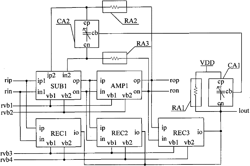
[0046] Such as figure 1 Shown is a schematic diagram of the circuit structure of Embodiment 1 of the logarithmic amplifier of the present invention. The logarithmic amplifier of the present invention comprises: subtractor SUB1, amplifier AMP1, rectifier REC1, REC2, REC3, and the output low-pass filter that is made up of variable capacitance array CA1 and resistance array RA1, by variable capacitance array CA2, resistance array RA2 and the low-pass filter of the feedback network composed of resistor array RA3.
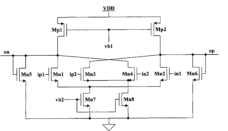
[0047] Wherein the number of subtractors is at least one, and this embodiment takes one subtractor as an example, and it can also be multiple; the number of amplifiers is at least one, and this embodiment takes one amplifier as an example; the number of rectifiers is at least three, and this implementation Example Take three rectifiers as an example. The subtractor and the amplifier in this embodiment adopt a folded subtractor and amplifier; the rectifier adopts a rec...
Embodiment 2
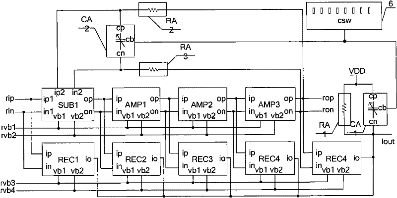
[0055] Such as figure 2 As shown, it is a schematic diagram of the circuit structure of Embodiment 2 of the logarithmic amplifier of the present invention; the difference between this embodiment and Embodiment 1 is that this embodiment also includes: amplifiers AMP2 and AMP3, rectifiers REC4 and REC5, and a time constant correction circuit 9 .
[0056] Among them, the differential input terminals ip and in of AMP2 are respectively connected with the differential output terminals op and on of AMP1; the differential input terminals ip and in of AMP3 are respectively connected with the differential output terminals op and on of AMP2; the differential output terminals op of AMP3 , on are respectively connected to the differential output terminals rop and ron of the logarithmic amplifier; the first bias voltage input terminal vb1 of AMP1, the first bias voltage input terminal vb1 of AMP2, the first bias voltage input terminal vb1 of AMP3 and After the first bias voltage input ter...
PUM
 Abstract
Description
Claims
Application Information