Underwater sound channel effective sound velocity estimating method based on intrinsic sound ray visual search

An underwater acoustic channel and intrinsic sound ray technology, which is applied in the measurement of ultrasonic/sonic/infrasonic waves, measurement of propagation velocity, measurement devices, etc., can solve the problems of inaccurate effective sound velocity, consideration of sea surface reflection, and large amount of calculation.

Inactive Publication Date: 2010-07-14
HARBIN ENG UNIV
View PDF1 Cites 15 Cited by
  • Summary
  • Abstract
  • Description
  • Claims
  • Application Information

AI Technical Summary

Problems solved by technology

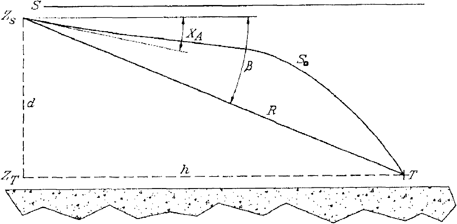
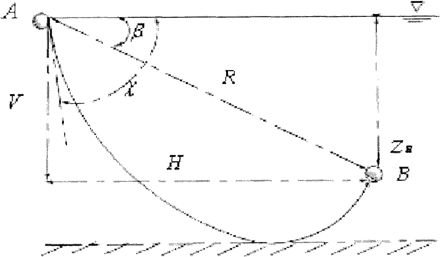
When Vincent studied deep sea acoustic positioning, he defined the sound velocity between any two points in ocean space as the effective sound velocity for the first time ([1] Vincent, H.T. and Hu, S.L.J., "Method and system for determining underwater effective sound velocity, "United States patent application, Patent No: US 6388948B1) and proposed a method for calculating the effective velocity of sound, but this method is only applicable to the solution of the effective velocity of sound in the area where the direct wave is located
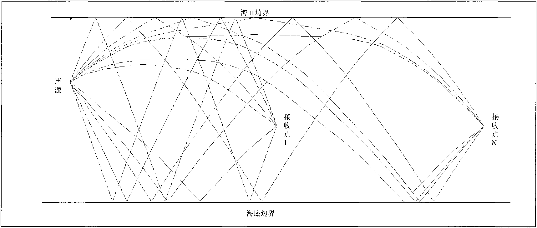
Sun Wanqing ([2] Shallow Sea Acoustic Positioning Technology and Application Research. Doctoral Dissertation of Ocean University of China. 2007: 88-91) proposed an effective sound velocity estimation method based on finite state automata. reflection,

Method used


Image

  • Underwater sound channel effective sound velocity estimating method based on intrinsic sound ray visual search
  • Underwater sound channel effective sound velocity estimating method based on intrinsic sound ray visual search
  • Underwater sound channel effective sound velocity estimating method based on intrinsic sound ray visual search

Examples


Embodiment Construction

[0033] The present invention is described in more detail below in conjunction with accompanying drawing example:

[0034] In a certain marine environment, the flow chart for estimating the effective sound velocity is as follows figure 2 As shown, the main steps are:

[0035] 1. The process of initializing basic parameters mainly includes the initialization of marine environment parameters:

[0036] (a) The water depth is 90m, the sea state is level 2, the seabed is flat, and the density of the seabed is 2.036kg / m 3 , The speed of sound at the bottom of the sea is 1836m / s; the reflection coefficient of the sea surface is -0.9;

[0037] (b) The vertical distribution of sound velocity is as attached image 3 As shown, it is divided into several layers;

[0038] (c) The spatial sampling range of the receiving hydrophone is 100-5000m, and the horizontal sampling interval is 10m;

[0039] (d) Set the initial grazing angle to traverse the effective space as [-60°, 60°].

[0040...


PUM


Abstract

The invention relates to an underwater sound channel effective sound velocity estimating method based on intrinsic sound ray visual search. A sound ray emitted from a sound source is tracked according to different glancing angles, when a receiving point depth is achieved and the energy constraint condition is met, multi-route identification is carried out on the sound ray to obtain an equivalent sound velocity. After self-adaptive variable-step ergodic in an initial glancing angle effective space is finished, interpolation fitting is carried out on various multi-route reaching sound ray equivalent sound velocity. Finally, the equivalent sound velocities of sampling points in each space are compared to take a maximum value and obtain the effective sound velocity of the point, the intrinsicsound ray visual search of each sampling point in the space area is realized, the effective sound velocity of each sampling point is stored in a matrix, and the effective sound velocity of any two points can be quickly and accurately acquired through the interpolation fitting. The method ensures that the effective sound velocity can be accurately acquired when a complex multi-route reaches the structure by adopting the mechanisms of self-adaptive variable-step ergodic in the initial glancing angle effective space, energy restraining and multi-route identification. The intrinsic sound ray visual search mechanism is utilized to avoid the frequency calculation of a sound field and better fuse accuracy, the adaptability and velocity.

Description

technical field [0001] The invention belongs to the technical field of underwater acoustic propagation and underwater acoustic positioning, and in particular relates to an effective sound velocity estimation method for sound waves propagating between arbitrary two points in an underwater acoustic channel. Background technique [0002] The study on sound velocity in water medium is the earliest quantitative study of hydroacoustics. In 1827, Colladon and Sturm measured the speed of sound waves in water in Lake Geneva, and the results obtained were close to modern estimates. Under the impetus of hydroacoustic ranging and echo sounding technology, some people measured the sound speed value in the ocean more accurately in the following period of time. Studies have shown that the sound velocity in the ocean has the property of vertical stratification. In practical engineering applications, the change of sound velocity with depth, or the functional relationship between sound veloc...

Claims


Application Information

Patent Timeline
IPC IPC(8): H04B13/02G01H5/00
Inventor 梁国龙林旺生王燕付进张光普
Owner HARBIN ENG UNIV
Why Eureka
Try Eureka