Eureka AIR delivers breakthrough ideas for toughest innovation challenges, trusted by R&D personnel around the world.

Low-noise planetary gearbox of wind driven generator

A technology for wind turbines and planetary gears, which is applied to wind turbine components, wind engines, engines, etc., and can solve problems such as inability to transmit torque normally, high noise, and uneven force on the sun gear

Inactive Publication Date: 2010-07-21
王光顺
View PDF1 Cites 4 Cited by
  • Summary
  • Abstract
  • Description
  • Claims
  • Application Information

AI Technical Summary

Problems solved by technology

However, due to the rigid fixed connection between the inner ring gear and the outer casing, the noise of the inner gear rotation is mostly transmitted through the inner ring gear and the outer casing, and the noise is large
In addition, at least two gears of different sizes must be installed on the planetary shaft. In terms of processing technology, it is impossible to process the two gears and the planetary shaft into an integrated structure. The gears and the planetary shaft usually adopt interference fit, which utilizes thermal expansion. The principle of cold shrinkage fixes the gear on the planetary shaft. This connection method is also a rigid connection. When the gear is subjected to a short-term large impact, it is easy to break the teeth, which cannot transmit torque normally and is difficult to adjust; output The shaft adopts a cantilever structure, which is prone to non-parallel swings, causing uneven force on the sun gear, premature wear, and affecting the service life

Method used


Image

  • Low-noise planetary gearbox of wind driven generator
  • Low-noise planetary gearbox of wind driven generator
  • Low-noise planetary gearbox of wind driven generator

Examples


Embodiment Construction

[0012] The present invention will be further described below in conjunction with the drawings and specific embodiments.

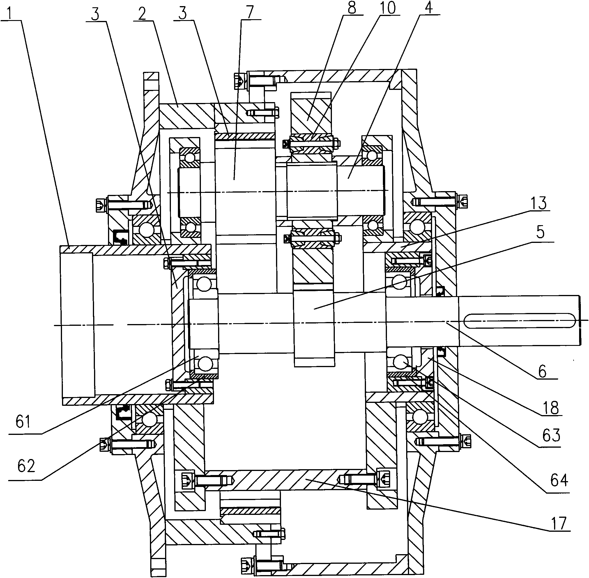
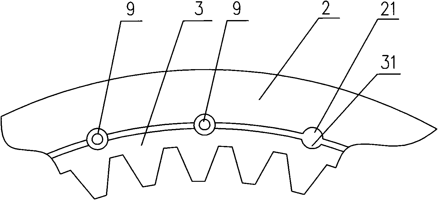
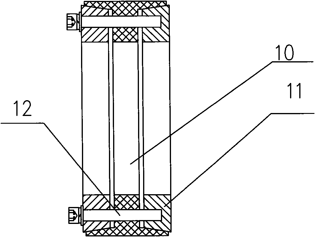
[0013] As shown in the drawings, the low-noise planetary gear speed-increasing box of the wind generator according to the present invention includes an input shaft 1, a box body 2, an inner ring gear 3, a planetary gear shaft 4, a central shaft 6, and a planet carrier 17. The planet carrier 17 has a barrel-shaped structure, and the outer wall of the planet carrier 17 is provided with hollow holes to facilitate gear meshing. The input shaft 1 and the planet carrier 17 are coaxial and fixedly connected together. More than two planetary gear shafts 4 are evenly distributed and installed in parallel on the planetary carrier through the bearing support. Three planetary gear shafts 4 can be evenly distributed around the axis of the planetary carrier 17 or more. A small planetary gear 7 and a large planetary gear 8 are fixedly installed on the planetary gear shaft 4...


PUM


Abstract

The invention relates to a speed increasing box, in particular to a low-noise planetary gearbox of a wind driven generator, which comprises an input shaft, a box body, an inner gear ring, a planet gear shaft, a center shaft and a planet carrier. The input shaft is fixedly connected with the planet carrier in a coaxial way. More than two planet gear shafts are uniformly distributed on the planet carrier through bearings. A large planetary gear and a small planetary gear are fixedly arranged on the planet gear shaft. The inner gear ring is fixed and arranged inside the box body. The small planetary gear is normally engaged with the inner gear ring. A sun gear is fixed and arranged on the center shaft. The large planetary gear is normally engaged with the sun gear. The input shaft is connected with the box body through the bearing. The outer diameter of the inner gear ring is smaller than the inner diameter of the box body. A plurality of box body pin grooves are uniformly distributed on the inner wall of the box body in the circumferential direction. The outer wall of the inner gear ring is provided with an inner gear ring pin groove. An elastic pin is embedded between the box body pin groove and the inner gear ring pin groove. The low-noise planetary gearbox of the wind driven generator has the advantages of low noise, long service life, strong shock resistance capability and low production and processing difficulty.

Description

Technical field [0001] The invention relates to a speed increasing box, in particular to a low noise planetary gear speed increasing box of a wind generator. Background technique [0002] The structure of the low-noise planetary gear speed-increasing box of the wind power generator is that a number of planetary gears are arranged around the sun gear, and the input shaft drives the planetary gears to rotate around the sun gear to drive the output shaft to rotate. This kind of gearbox is characterized by a large gear ratio. For example, Chinese patent 200820100520.x discloses a "dual planetary dual-arm wind power speed increasing gearbox". It has the characteristics of compact structure, small volume and large gear ratio. However, due to the rigid fixed connection between the inner gear ring and the housing, most of the noise from the rotation of the internal gear is transmitted through the inner gear ring and the housing, and the noise is large. In addition, at least two gears ...

Claims


Application Information

Patent Timeline
IPC IPC(8): F03D11/00F16H1/28F03D15/00
CPCF16H2001/2881F16H1/28F16H57/0006
Inventor 王光顺
Owner 王光顺
Why Eureka
Eureka Blog
Learn More