Oil-saving ignition method for fault coal and pulverized coal burner applying method

A pulverized coal burner, the technology of the burner, which is applied in the direction of the burner, burner, combustion ignition, etc. of burning powder fuel

Inactive Publication Date: 2010-07-21
艾佩克斯科技(北京)有限公司
View PDF3 Cites 5 Cited by
  • Summary
  • Abstract
  • Description
  • Claims
  • Application Information

AI Technical Summary

Problems solved by technology

But for lean coal, anthracite and other low-quality co

Method used


Image

  • Oil-saving ignition method for fault coal and pulverized coal burner applying method
  • Oil-saving ignition method for fault coal and pulverized coal burner applying method
  • Oil-saving ignition method for fault coal and pulverized coal burner applying method

Examples


Embodiment Construction

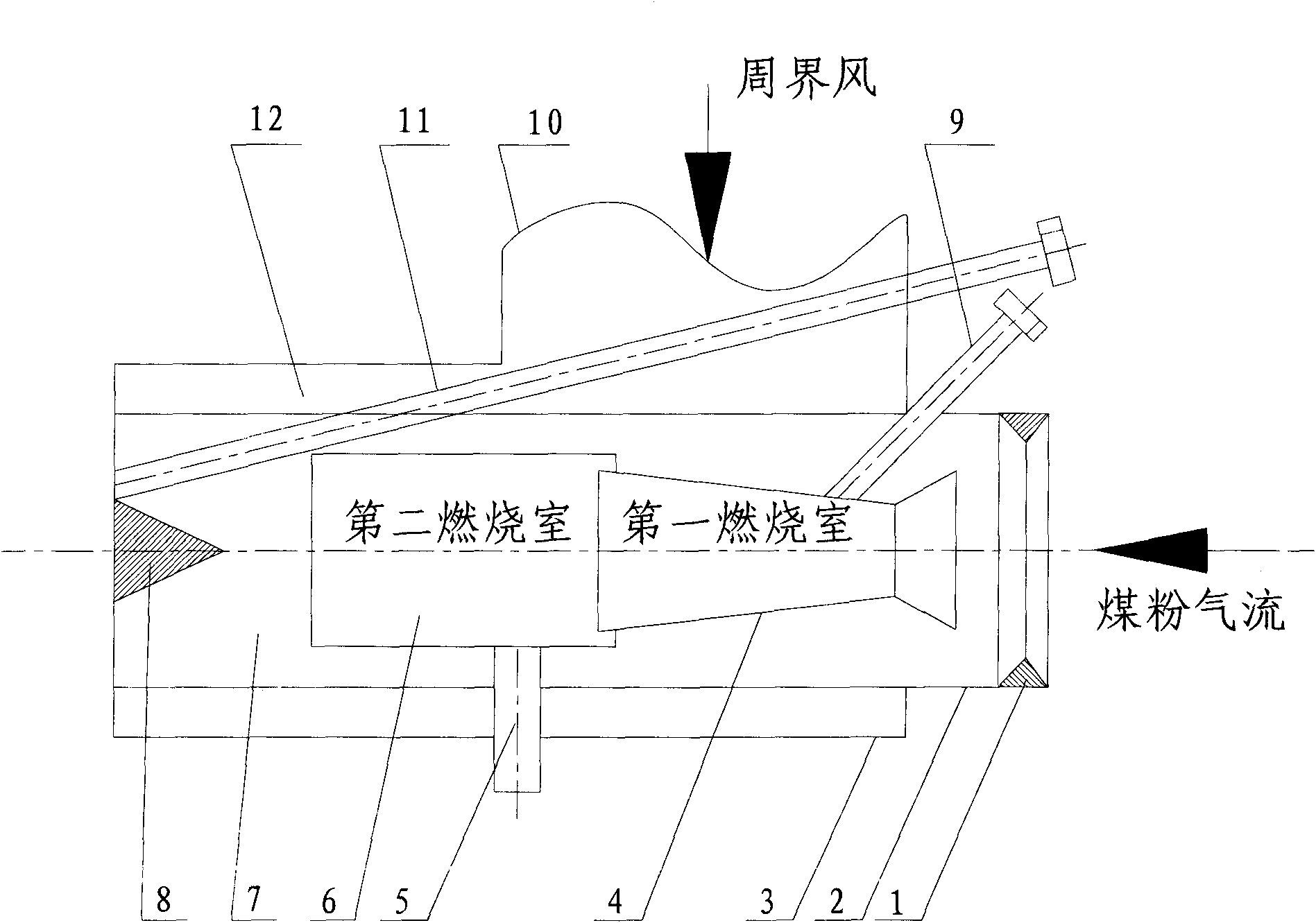
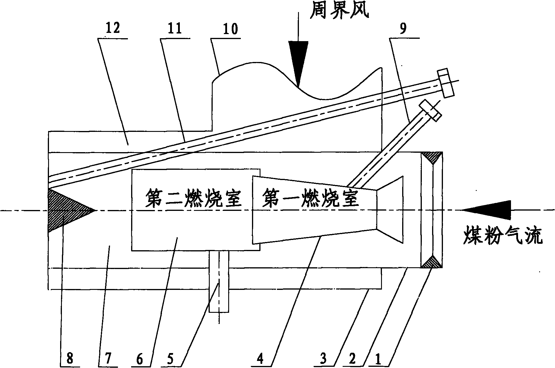
[0018] Such as figure 1 As shown, the pulverized coal burner of the present invention includes a pulverized coal concentration ring 1, a pulverized coal burner 2, a peripheral air cooling jacket 3, a primary combustion chamber 4, a secondary combustion chamber 6, and a tertiary combustion chamber 7, and the section is a triangular strip blunt body 8, main oil gun 9, air inlet 10, auxiliary oil gun 11; combustion chamber 4, 6, 7 is located on the axis of pulverized coal burner 2, and main oil gun 9 is inserted into a In the first-stage combustion chamber 4, the auxiliary oil gun 11 is inserted from the rear to the side of the blunt body 8 at the flame outlet of the pulverized coal burner 2, and the peripheral wind cooling jacket 3 is set on the outside of the pulverized coal burner 2. The imported fresh air cools the pulverized coal burner 2 shell.

[0019] In addition, in order to ensure the reliable operation of the pulverized coal burner, a flame monitoring device 5 is also...


PUM


Abstract

The invention discloses an oil-saving ignition method for fault coal and a pulverized coal burner applying the method. In the method, pulverized coal streams are ignited by using a small amount of fuel oil in the pulverized coal burner and at the outlet of the pulverized coal burner, and flames of the pulverized coal streams replace atomized torch flames of a big oil gun in the traditional ignition mode. The burner comprises a shell; a composite chamber and a main oil gun are arranged in the shell; an auxiliary oil gun is also arranged in the shell, and is arranged in a certain lower-level chamber at the rear end of the first-level chamber; and the pulverized coal body heated in the burner moves to the auxiliary oil gun and then is ignited by the auxiliary oil gun so as to form stable pulverized coal stream flames. The auxiliary oil gun is arranged at the rear end of the main oil gun in the burner, and the distance between the two oil guns is long enough, so the pulverized coal body can be reliably heated to the degree suitable for ignition and then is reliably ignited so as to achieve good oil-saving effect.

Description

technical field [0001] The invention relates to an oil-saving ignition method for low-quality coal and a pulverized coal burner using the method, in particular to an oil-saving ignition method for low-quality coal and a pulverized coal burner when a pulverized coal boiler of a thermal power generation unit is started in a cold state. technical background [0002] At present, the peak-to-valley difference in the power supply of major power grids in my country is increasing day by day. When the load is low, many large units must operate under low load, and small units must be shut down for backup. In the process of boiler start-up and low-load stable combustion, large oil guns are traditionally used, which consumes a lot of fuel. In order to save oil, more and more large coal-fired generating units need to be installed with oil-saving burners. At present, there have been many successful application examples of micro-oil ignition technology (or gasification small oil gun ignit...

Claims


Application Information

Patent Timeline
IPC IPC(8): F23Q9/00F23D1/00
Inventor 郭永浩姚文达李硕郭秀峰
Owner 艾佩克斯科技(北京)有限公司
Why Eureka
Try Eureka