Multiphase long-stator primary permanent magnet linear motor

A permanent magnet linear motor and stator technology, applied in the direction of electrical components, electromechanical devices, electric components, etc., can solve the problems of motor magnetic circuit and winding asymmetry, magnetic circuit and winding asymmetry, back EMF is not symmetrical, etc., to achieve structural Compactness, reduced thrust fluctuation, and high power density

Active Publication Date: 2010-07-21
SOUTHEAST UNIV
View PDF2 Cites 28 Cited by
  • Summary
  • Abstract
  • Description
  • Claims
  • Application Information

AI Technical Summary

Problems solved by technology

However, the traditional structural form causes the asymmetry of the magnetic circuit and winding of the motor, resulting in a non-symmetrical trapezoidal or square wave of the back EMF, and thus causes large fluctuations in the thrust of the motor
The purpose of this patent is to propose a primary permanent magnet linear motor with a new structure in view of the shortcomings of the asymmetrical magnetic circuit and winding of this type of linear motor.

Method used


Image

  • Multiphase long-stator primary permanent magnet linear motor
  • Multiphase long-stator primary permanent magnet linear motor
  • Multiphase long-stator primary permanent magnet linear motor

Examples


specific Embodiment approach 1

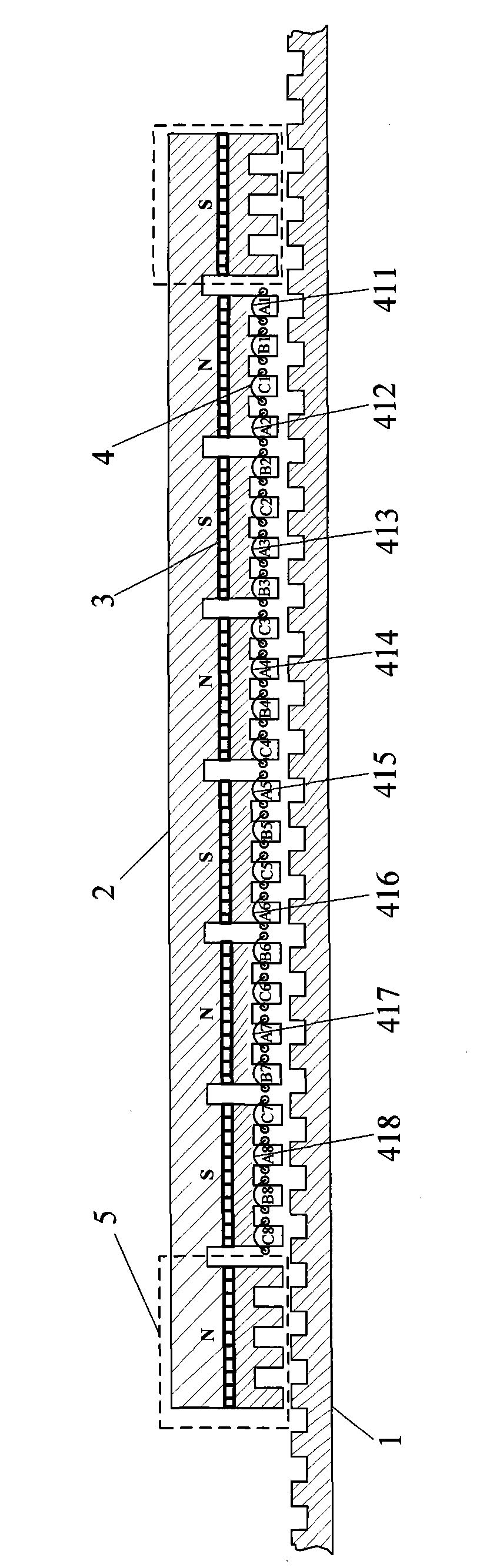
[0019] Specific implementation mode one: figure 1 It is a cross-sectional view of a 3-phase permanent magnet series-connected plate-type long stator primary permanent magnet linear motor designed by the technology of the present invention. If m=3, k=1, and j=1, the number of permanent magnets is N PM =2k×m+2=8, the number of teeth of the mover sleeve with winding is N mt =(N PM -2)(m+1)=24, the range of additional teeth at each end of the motor is between [2 and 4], and there is no winding on the additional teeth. τ p / τ s =m / (m-0.5j)=6 / 5 The permanent magnet is a flat plate structure, and adopts the parallel magnetization method. Each non-additional permanent magnet corresponds to m+1=4 teeth, wherein the concentrated windings on the first tooth and the fourth tooth belong to the same phase, and the windings on the remaining teeth belong to other phases in turn. The magnetization directions of adjacent permanent magnets are opposite.

[0020] The motor of the present in...

specific Embodiment approach 2

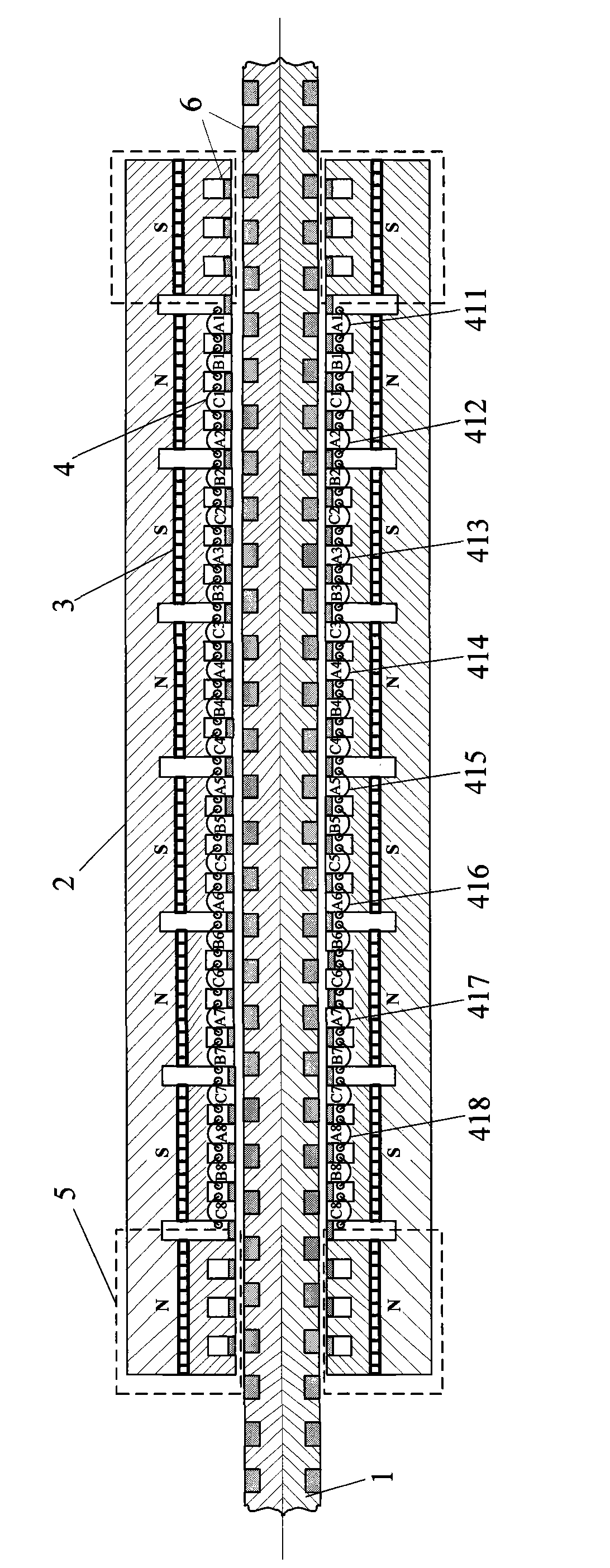
[0025] Specific implementation mode two: combination figure 1 , figure 2 This embodiment is described. The first difference between this embodiment and the specific embodiment is that the motor structure is a cylindrical structure. Its axial section view is as figure 2 shown. The stator 1 is a cylindrical structure, the mover 2 is a cylindrical structure, and the permanent magnet 3 is composed of a ring-shaped cylindrical permanent magnet material or N tile permanent magnet materials, and radial magnetization is adopted. 6 is a non-magnetic conductive material. When needed, 6 can be filled in the middle of the stator slot, and the stator is a slotless cylindrical structure at this time. At the same time, the winding groove of the mover is sealed with material 6, and the contact surface between the mover and the stator is also a smooth groove-free structure. Other composition and connection methods are the same as those in the first embodiment.

specific Embodiment approach 3

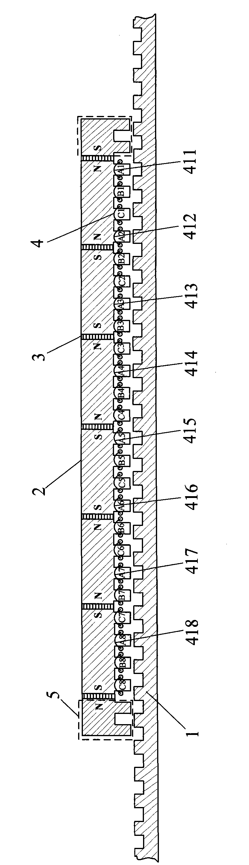
[0026] combine figure 1 , image 3 This embodiment is described. The first difference between this embodiment and the specific embodiment is that the permanent magnet of this motor adopts the second magnet placement method described in the technical solution. In this embodiment, m=3, k=1, j=1, then the number of permanent magnets is N PM =2k×m+1=7, the number of teeth of the mover sleeve with winding is N mt =(N PM -2)(m+1)=24, the number of additional teeth at both ends of the motor is between [2 and 4], and there is no winding on the additional teeth. τ p / τ s =m / (m-0.5j)=6 / 5, the permanent magnet is a flat plate structure, and adopts the parallel magnetization method. There are m+1=4 teeth between adjacent permanent magnets, wherein the concentrated windings on the first tooth and the fourth tooth belong to the same phase, and the windings on the remaining teeth belong to other phases in turn. The magnetization directions of adjacent permanent magnets are opposite. ...


PUM


Abstract

The invention relates to a multiphase long-stator primary permanent magnet linear motor which has the advantages of simple structure, firmness, stronger output thrust, higher power density and smaller thrust fluctuation. The motor comprises a stator (1), an air gap and rotors (2), wherein each rotor (2) comprises permanent magnets (3), a concentrated winding (4) and additional teeth (5); both the stator and the rotors are double-salient pole single-edges or double-edge flat-panel structures, and all concentrated winding coils of any phase are positioned in a rotor iron core slot; adjacent permanent magnets (3) form a serial magnetic circuit; the number of the permanent magnets (3) is NPM=2k*m+2, wherein k is a positive integer, and the number m of motor phases is not smaller than 3; both end parts of each rotor (2) are respectively provided with a permanent magnet which is an additional permanent magnet of each motor; the number of windings of the rotors is Nmt=(NPM-2)(m+1); and the central distance of adjacent teeth of the rotors is tau p.

Description

technical field [0001] The invention is a long-stator primary permanent magnet linear motor with simple structure, solid structure, strong output thrust, high power density and small thrust fluctuation, and relates to the technical field of motor manufacturing. Background technique [0002] The motor is the main part of the transmission system, and a reasonable selection of the motor can improve the performance and efficiency of the entire system. In linear applications, traditional rotary motors require certain mechanical transmission components to convert rotary motion into linear motion. This brings many problems, such as bulky system, increased weight, high noise, increased maintenance costs, and in rail transit applications, wheel-rail slippage will occur if the speed is too high. Therefore, the technical means of replacing the rotary motor with a linear motor can overcome the above-mentioned shortcomings of the rotary motor in this application and improve the efficien...

Claims


Application Information

Patent Timeline
Patent Type & Authority Applications(China)
IPC IPC(8): H02K41/02H02K1/14H02K1/26H02K1/27
Inventor 程明曹瑞武花为赵文祥
Owner SOUTHEAST UNIV
Why Eureka
Try Eureka