
Air purification part and device with air self-purification function

A technology of air purification and components, applied in the field of air purification, can solve problems such as secondary pollutants and excessive ozone concentration, and achieve the effects of reducing hazards, reducing maintenance costs, and low energy consumption

Inactive Publication Date: 2010-07-28
TSINGHUA UNIV
View PDF5 Cites 20 Cited by
  • Summary
  • Abstract
  • Description
  • Claims
  • Application Information

AI Technical Summary

Problems solved by technology

Most of the relevant research and patent achievements focus on the development and preparation of new photocatalysts and the design of various new reaction devices, but there is no product or application that uses this technology for pollutant removal in special environments
At the same time, the vacuum ultraviolet photocatalytic technology also has its shortcomings. There may be secondary pollutants in the catalytically degraded products, and the ozone concentration in the exhaust gas may exceed the standard.

Method used


Image

  • Air purification part and device with air self-purification function
  • Air purification part and device with air self-purification function
  • Air purification part and device with air self-purification function

Examples


Embodiment 1

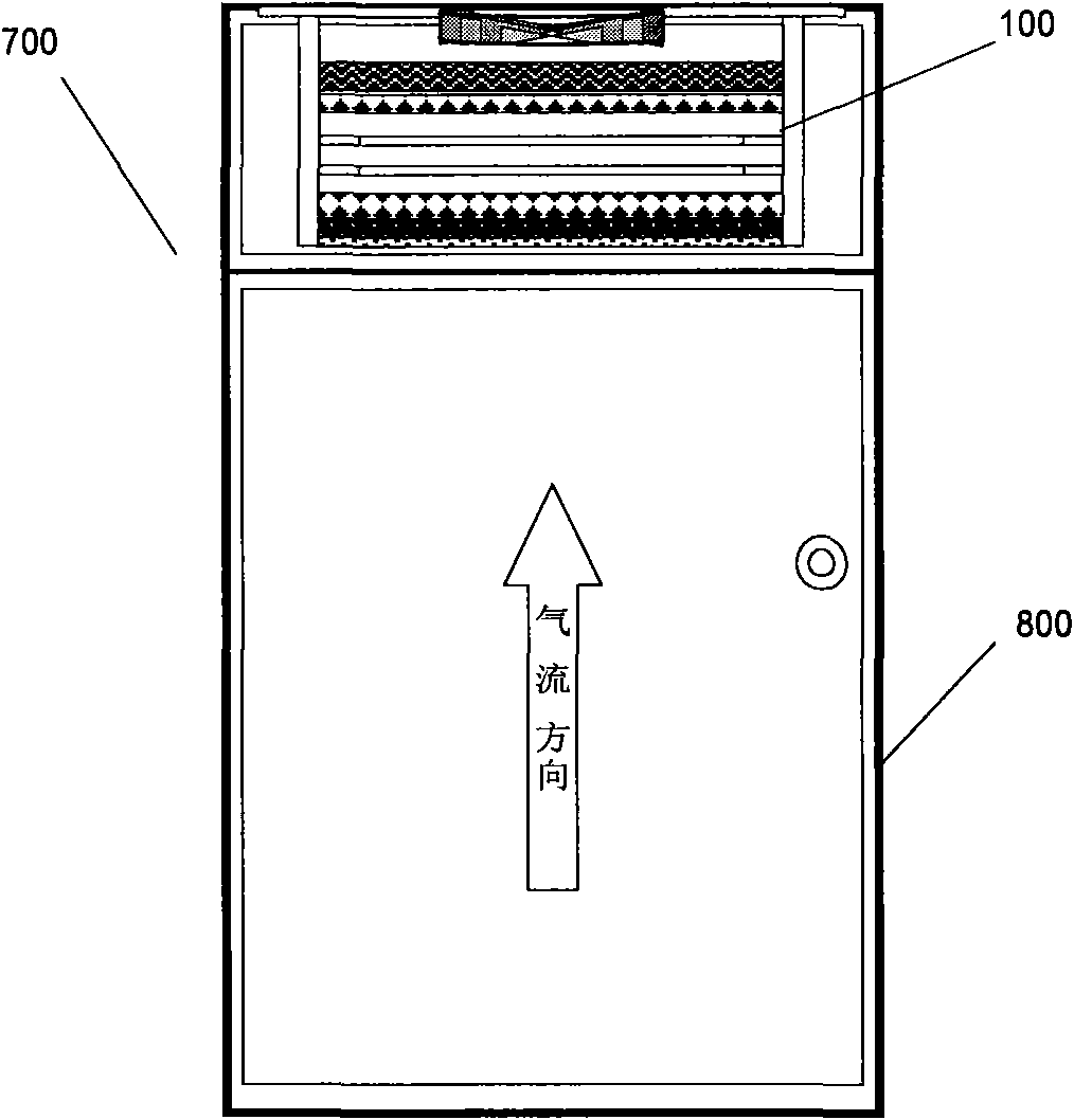
[0044] In this embodiment, the air cleaning unit 100 is applied to a device 700 with air self-purification function such as a medicine cabinet, the upper end of the medicine cabinet 700 has an opening, and the air cleaning unit 100 is installed on the top of the medicine cabinet 700, Form an air-purifying medicine cabinet with deodorization and purification functions, such as figure 2 shown. An axial flow fan can be selected in the air purification unit 100 to drive air circulation, so that the purified gas is directly discharged from the top of the medicine cabinet from bottom to top.

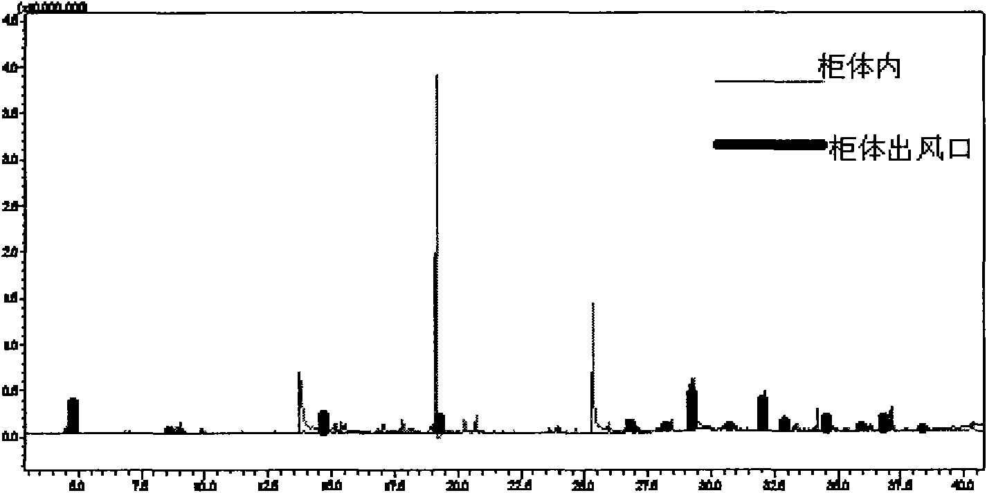
[0045] In the working state, the effect test is carried out on the medicine cabinet 700, air samples are collected in the cabinet body 800 and the air outlet of the cabinet body 800 respectively, and the gas chromatography-mass spectrometry analysis is performed, and the results of the gas chromatography-mass spectrometry analysis are shown in image 3 middle. As shown in 3, before the air ...

Embodiment 2

[0047] Apply the air purification unit 100 according to one embodiment of the present invention to a chemical laboratory fume hood 1700, and add rollers 1900 to form a movable fume hood 1700, such as Figure 4 shown. It is characterized in that it does not need to be connected with the ventilation duct of the building, and can be freely moved to different rooms and locations according to the operation needs.

Embodiment 3

[0049] In this embodiment, the air purification unit 100 is applied to the laboratory operating table to form a deodorizing operating table 2700, such as Figure 5 shown. The air purification unit 100 is installed at the bottom of the deodorizing console 2700, and an air drive unit such as a centrifugal fan 2500 is used to discharge the purified gas from both sides of the deodorizing console 2700 respectively.


PUM

PropertyMeasurementUnit
wavelengthaaaaaaaaaa

Abstract

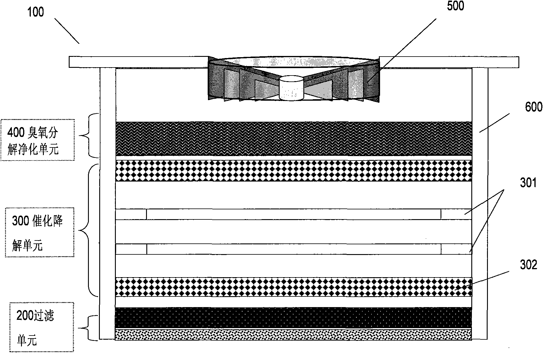
The invention discloses an air purification part, which comprises a filtering unit used for filtering polluted air, a catalyzing and degrading unit capable of generating ozone and carrying out a light-catalyzed reaction so as to catalyze and degrade the filtered air, and an ozone decomposition and purification unit used for purifying the ozone in the catalyzed and degraded air and releasing the purified air. The invention further discloses a device with an air self-purification function. The air purification part and the device fully develop the advantages of the low energy consumption and high degradation rate of vacuum ultraviolet catalysis, fully degrade the polluted air and perform advanced purification on secondary pollutants and unnecessary ozone produced by the polluted air in combination with ozone catalyzing and degrading technology, thereby reducing the damage of the polluted air to the environment and providing a more healthier working environment for workers.

Description

technical field [0001] The invention relates to the technical field of air purification, in particular to an air purification component and a device with an air self-purification function. Background technique [0002] Chemical pollutants in indoor air are harmful to human health. Even low concentrations of volatile organic compounds (VOCs) can cause acute / chronic diseases. Benzene, formaldehyde, trichloroethane, trichlorethylene, polychlorinated biphenyls ( PCB) have been identified as carcinogens. Therefore, my country's "Indoor Air Quality Standards (GB / T18883-2002)" clearly stipulates the minimum limits of various air pollutants. In some special microenvironments, such as chemical laboratories, biological laboratories, medical laboratories and hospitals, the concentration and types of volatile organic pollutants in the air are much higher than those in general places, and the pollution sources mainly come from chemicals, reagents, etc. A large number of storage and fre...

Claims


Application Information

Patent Timeline
Patent Type & Authority Applications(China)
IPC IPC(8): A61L9/20A61L9/015A61L9/014A61L9/00B01D46/12B01D46/30A61L101/02A61L101/04A61L101/10A61L101/24A61L101/30
Inventor 张彭义张博
Owner TSINGHUA UNIV
Learn More