Telescopic double-edged deep-hole boring cutter

A telescopic, deep-hole technology, which is applied to the accessories of tool holders, tools for lathes, turning equipment, etc., can solve the problems of difficult processing, achieve good quality, accurate feed, and reduce self-excited vibration.

Inactive Publication Date: 2010-07-28
CHENGDU AIRCRAFT INDUSTRY GROUP +1
View PDF0 Cites 28 Cited by
  • Summary
  • Abstract
  • Description
  • Claims
  • Application Information

AI Technical Summary

Problems solved by technology

To solve the problem of difficulty in processing large length-to-diameter ratio deep hole bottle cavity

Method used


Image

  • Telescopic double-edged deep-hole boring cutter
  • Telescopic double-edged deep-hole boring cutter
  • Telescopic double-edged deep-hole boring cutter

Examples


Embodiment 1

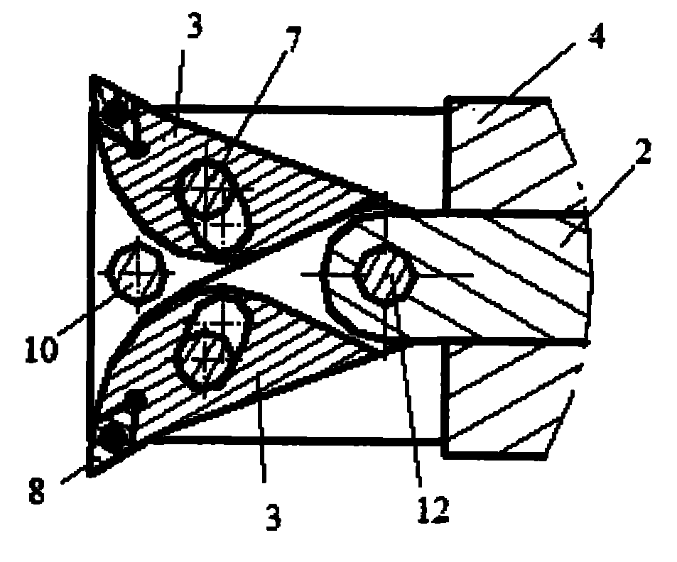
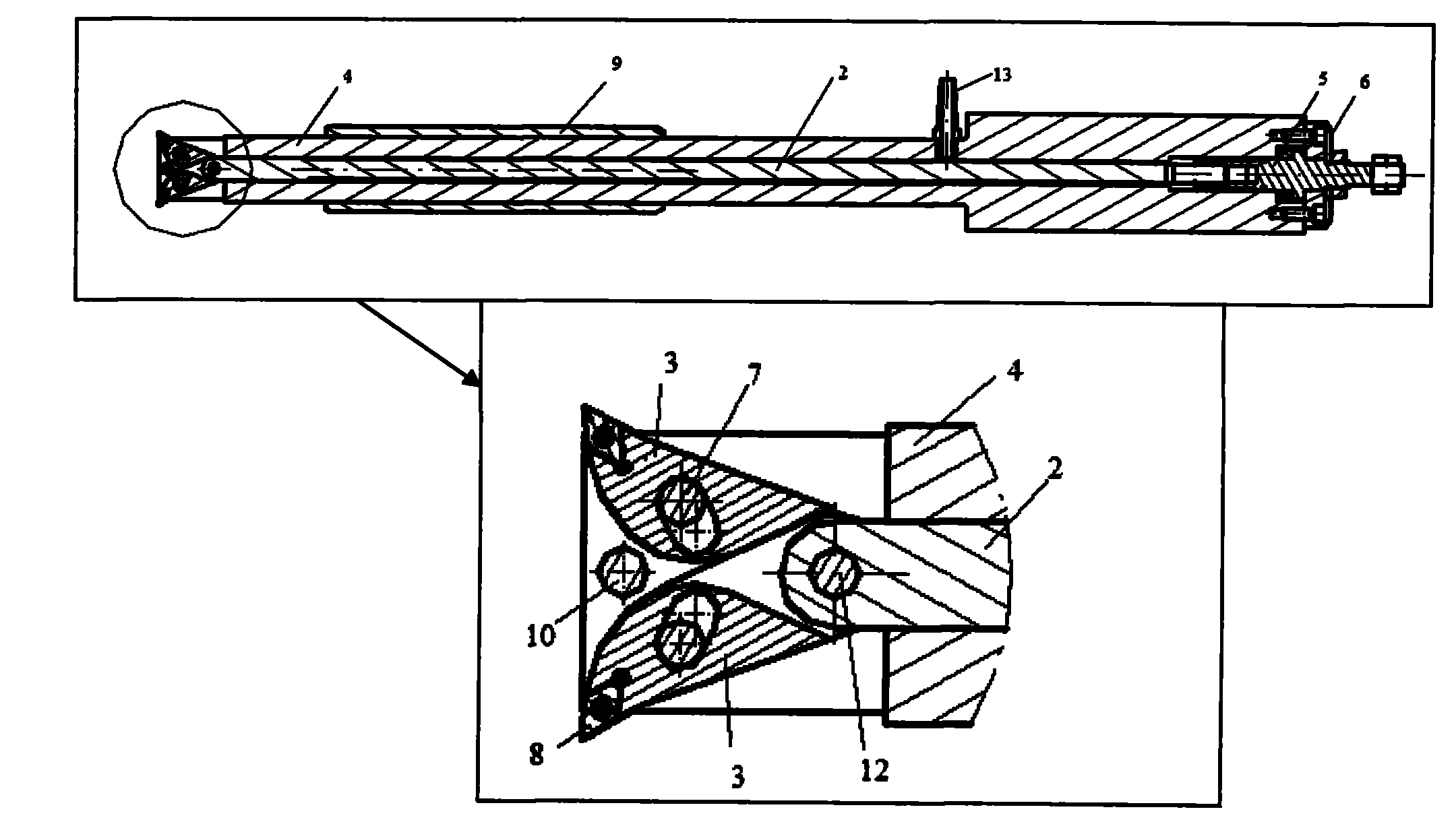
[0030] exist image 3 In the shown embodiment, the length-to-diameter ratio of the telescopic double-edged boring tool and boring bar is as high as 12. The overhang is 600mm and the diameter is 50mm. The handwheel 1 is fixed on the screw rod 5 by a key, and the screw rod 5 is threadedly connected with the push rod 2 and installed in the axis through hole of the boring bar 4 . Guide sleeve 9 is enclosed within boring bar 4 outsides. The cutter head 3 is connected with the push rod 2 with a pin, and the pin 7 passes through the chute of the cutter head 3 and is fixed on the boring bar 4 . Screw 10 is also fixed on the boring bar for compressing the cutter head 3 . The boring bar 4 is provided with a coolant nozzle 13 connected to the through hole of the axis, and the coolant nozzle 13 is fixed on the boring bar 4 as the inlet of the coolant. The blade 8 is installed on the cutter head 3 .

Embodiment 2

[0032] exist Figure 4 In the example shown. The length-to-diameter ratio of the boring tool is 17. The overhang is 990mm and the diameter is 58mm.

[0033] Hand wheel 1 is identical with the telescopic double-edged boring tool of described embodiment, (not shown in the figure), screw rod 5 is connected with push rod 2 with screw thread and is contained in boring bar 4 inside. Guide sleeve 9 is enclosed within boring bar 4 outsides. The cutter head 3 is connected with the push rod 2 by a pin, and the pin 7 passes through the chute of the cutter head 3 and is fixed on the boring bar 4 . The screw 10 used to compress the cutter head 3 is fixed on the boring bar 4 . Coolant spray head 13 is fixed on the boring bar 4, as the entrance of coolant. The blade 8 is installed on the cutter head 3 .

Embodiment 3

[0035] exist Figure 5 In the example shown. The length-to-diameter ratio of the boring tool is 8.9. The overhang is 760mm and the diameter is 85mm.

[0036] The handwheel 1 is identical to the telescopic double-edged boring tool of the first embodiment (not shown). Screw rod 5 and push rod 2 are connected with threads and installed inside boring bar 4 . The cutter head 3 is connected with the push rod 2 with a pin, and the pin 7 passes through the chute of the cutter head 3 and is fixed on the boring bar 4 . The screw 10 for pressing the cutter head 3 is also fixed on the boring bar 4 . Coolant spray head 13 is fixed on the boring bar 4, as the entrance of coolant. The blade 8 is installed on the cutter head 3 .


PUM


Abstract

The invention provides a telescopic double-edged deep-hole boring cutter, aims to provide a deep-hole drilling boring cutter which has large length-diameter ratio, small self-excited vibration of a boring bar, reliable and stable feeding operation, no radial motion of a cutter arbor, and radial feeding of a cutting edge in a cutting process, and solves the problem that the deep-hole bottle cavity with large length-diameter ratio has large processing difficulty. The boring cutter comprises the boring bar which can extend to the deep-hole bottle cavity, wherein the central axis of the boring bar is provided with a through hole which runs through the central axis; a push rod (2) which is connected with a radial feeding device of the head of the boring bar is arranged in the through hole; the rear end of the push rod (2) is provided with a rotating handle; the rotating handle rotates a screw (5) and pushes the push rod (2) to do radial telescopic motion in the through hole of the boring bar; and the push rod (2) moves by way of pushing or pulling to drive the radial feeding device connected with the push rod and adjust the cutting edge of the double-edged boring cutter on a cutter block (3) to radically feed in the deep-hole bottle cavity.

Description

technical field [0001] The invention relates to a telescopic double-edged deep-hole boring tool system for processing deep-hole bottle cavities. Background technique [0002] Deep hole machining is a recognized technical problem in the field of metal cutting, and sometimes product performance has to be sacrificed to meet the processing technology requirements. The bottle cavity at the bottom of the deep hole is more difficult to process, and the structure of the bottle cavity further restricts the diameter of the boring bar, and the structure is further restricted. During the boring process of the hole, the boring bar with the aspect ratio less than 4 will not produce vibration when machining the workpiece. When the length-to-diameter ratio of the boring bar increases from 4 to 10, the rigidity of the boring bar itself obviously cannot meet the processing requirements. During the boring process, because the boring bar is subjected to continuous cutting force, the boring ba...

Claims


Application Information

Patent Timeline
Patent Type & Authority Applications(China)
IPC IPC(8): B23B27/00
Inventor 张文光赵苏军张林丁国富谢斌斌江磊
Owner CHENGDU AIRCRAFT INDUSTRY GROUP
Why Eureka
Try Eureka