
Screw rods for PIN-type three-screw extruder

A three-screw and extruder technology, which is applied in the field of screw structure, can solve the problems of affecting the performance of finished materials, the performance of finished materials, the shortening of molecular chains, etc., and achieve the effect of strengthening, improving and good performance

Active Publication Date: 2012-11-28
石家庄德倍隆科技有限公司
View PDF2 Cites 0 Cited by
  • Summary
  • Abstract
  • Description
  • Claims
  • Application Information

AI Technical Summary

Problems solved by technology

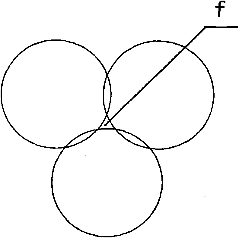
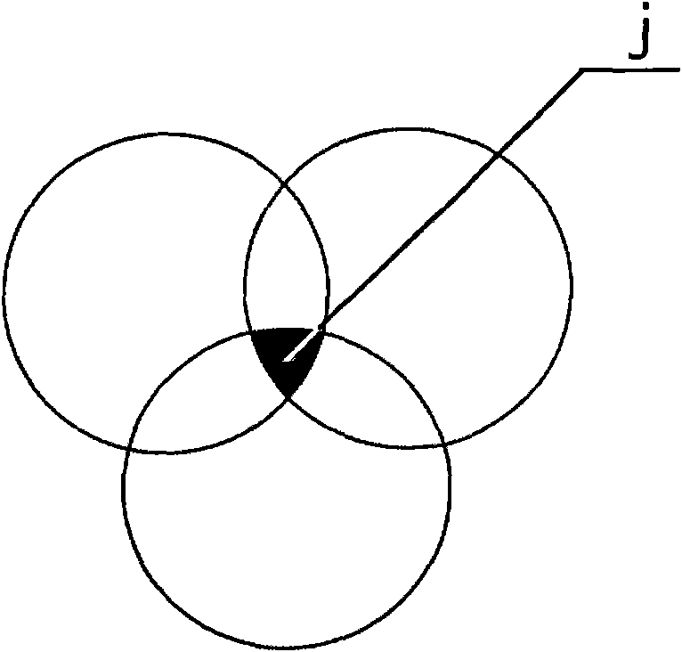
When the three-line threaded element with common groove depth ratio is engaged in conjugate engagement, a central closed area will appear. Since the outer circle formed by the threaded element during the rotating engagement process cannot cover the closed area, the material cannot be affected by the thread in it. The shearing and extrusion of the components, therefore, the material in the central area is directly extruded, and rarely exchanges with the material flow outside the area, and the mixing effect is poor, which directly affects the performance of the finished material
In addition, the pressure building mode of the traditional three-screw output terminal adopts a large number of counter-rotating meshing blocks. When the pressure is built up, the shear is too strong, causing the material to age and decompose or the molecular chain to be shortened, and the performance of the finished material is reduced.

Method used


Image

  • Screw rods for PIN-type three-screw extruder
  • Screw rods for PIN-type three-screw extruder
  • Screw rods for PIN-type three-screw extruder

Examples


Embodiment 1

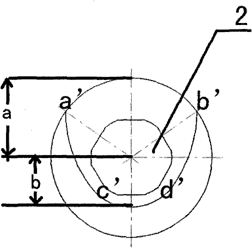
[0035] Depend on image 3 , Figure 4 As can be seen from the illustration, the screw used in the pin-shaped three-screw extruder of this embodiment is composed of a screw mandrel 2 and a threaded element 1 set on the screw mandrel 2, and the threaded elements 1 of the three screws are conjugate Engagement, and the shape of the threaded elements 1 that engage with each other is the same, the outer circle radius formed by the rotation of the threaded element 1 is a=3.0cm, the inner circle radius is b=2cm, and the center distance of the three screws is 5cm. The threaded element 1 is a single-line helical block, which is formed by rotating a single-line helical piece 3 with a certain thickness with the axis of the screw mandrel 2 as the center line. , the inner circle arc c'd' and the transition line a'c' and b'd' connecting the outer circle arc a'b' and the inner circle arc c'd', and the transition line a' c' and b'd' are arranged symmetrically.

[0036] Depend on Figure 5 ...

Embodiment 2

[0039] Depend on Figure 6 , Figure 7 It can be seen that the difference from Embodiment 1 is that the threaded element 1 is a single-wire engagement block, which is formed by rotating a plurality (seven in this embodiment) of single-wire engagement pieces 4 with a certain thickness. The shape of the end face of the engagement piece 4 is identical to that of the single-wire helical piece 3 in Embodiment 1, that is, the end surface of the single-line engagement piece is surrounded by an outer circular arc, an inner circular arc, and a transition line connected between the outer circular arc and the inner circular arc. , and the transition line is set symmetrically. At this time, the same straight line where the radius of the outer circle arc and the radius of the inner circle arc is set as the rotation reference line m, the single-line engagement piece takes the axis of the screw mandrel as the center line of rotation, and each single-line engagement piece is engaged with the...

Embodiment 3

[0041] Depend on Figure 8 , Figure 9It can be seen that the difference from Embodiment 1 is that the threaded element 1 is an equilateral three-wire eccentric engagement block, and the equilateral three-wire eccentric engagement block is composed of a plurality of (this embodiment is 5) equilateral three-wire eccentric engagement blocks with a certain thickness. The meshing piece 5 is rotated, and the shape of the end surface of the equilateral three-line eccentric meshing piece 5 has three corner points, and the corner points are connected by the same transition line, and one of the corner points is used as a point forming the outer circle track of the rotary block. The distance from the point extending from the axis to the transition line is equal to a+b, and the straight line where the distance is located is defined as the reference line of rotation. The equilateral three-line eccentric engagement piece takes the axis of the screw mandrel as the rotation center line, and ...


PUM


Abstract

The invention relates to a screw rod structure, in particular to screw rods used on a PIN-type three-screw extruder. Each screw rod of the extruder is composed of a screw rod mandrel (2) and a threaded element (1) sheathed on the screw rod mandrel. Threaded elements (1) of the three screw rods are meshed with each other in a conjugate manner, and the shapes of the meshed parts of the threaded elements (1) are the same. The semi-diameter of an outer circle formed by the rotating of each threaded element (1) is a, the semi-diameter of an inner circle is b, and a / b is larger than 1.3 and smallerthan 2.15. By adopting the above technical scheme, an overlapped zone of motion traces of the outer diameter of the meshed threaded elements on the three screw rods becomes larger and larger along with the increasing of the groove depth ratio; even if the three screw rods cause a meshing enclosed zone to disappear due to improper design of the tooth shape, materials in a central material zone cancarry out forced flowing exchange with external materials and actively participate in plasticizing and milling, thereby improving the performance of finished materials.

Description

technical field [0001] The invention relates to a screw structure, in particular to a screw used in a pin-shaped three-screw extruder. Background technique [0002] At present, in the field of plastic compounding, parallel twin-screw extruders are commonly used, and its transmission is a parallel two-axis output. With the continuous development of the modern plastic industry, especially the wide application of high-filling and high-dispersion materials and the requirements for low energy consumption, rubber and plastic processing equipment is developing in the direction of diversification and multi-screw. Compared with the traditional twin-screw extrusion system, the three-screw extrusion system has better splitting effect and more times of shearing, that is, better distribution mixing and dispersion mixing, and has a larger exhaust interface area, which is more conducive to exhaust operation , which minimizes the impact of exhaust on output and has the advantages of lower ...

Claims


Application Information

Patent Timeline
Patent Type & Authority Patents(China)
IPC IPC(8): B29C47/60B29C47/40B29C48/52B29C48/59
CPCB29C47/6018B29C47/6056B29C47/6075B29C47/6012B29C48/52B29C48/53B29C48/57B29C48/59B29C48/43
Inventor 崔鹏
Owner 石家庄德倍隆科技有限公司
Learn More