
Optical time domain reflection (OTDR) distributed optical fiber sensing system based on Brillouin scattering and subsurface temperature monitoring method using same
A technology of optical time domain reflection and distributed optical fiber, which is applied in the direction of physical/chemical change thermometers, thermometers, measuring devices, etc., and can solve problems such as poor stability, complex structure, and poor corrosion resistance
Patent Information
- Authority / Receiving Office
- CN · China
- Patent Type
- Patents(China)
- Current Assignee / Owner
- Publication Date
- 2013-05-08
- Estimated Expiration
- Not applicable · inactive patent
Smart Images
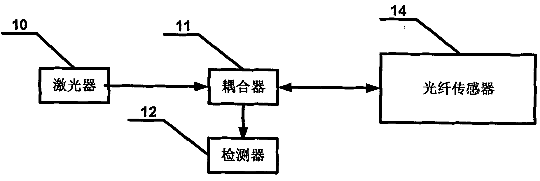
Figure 1 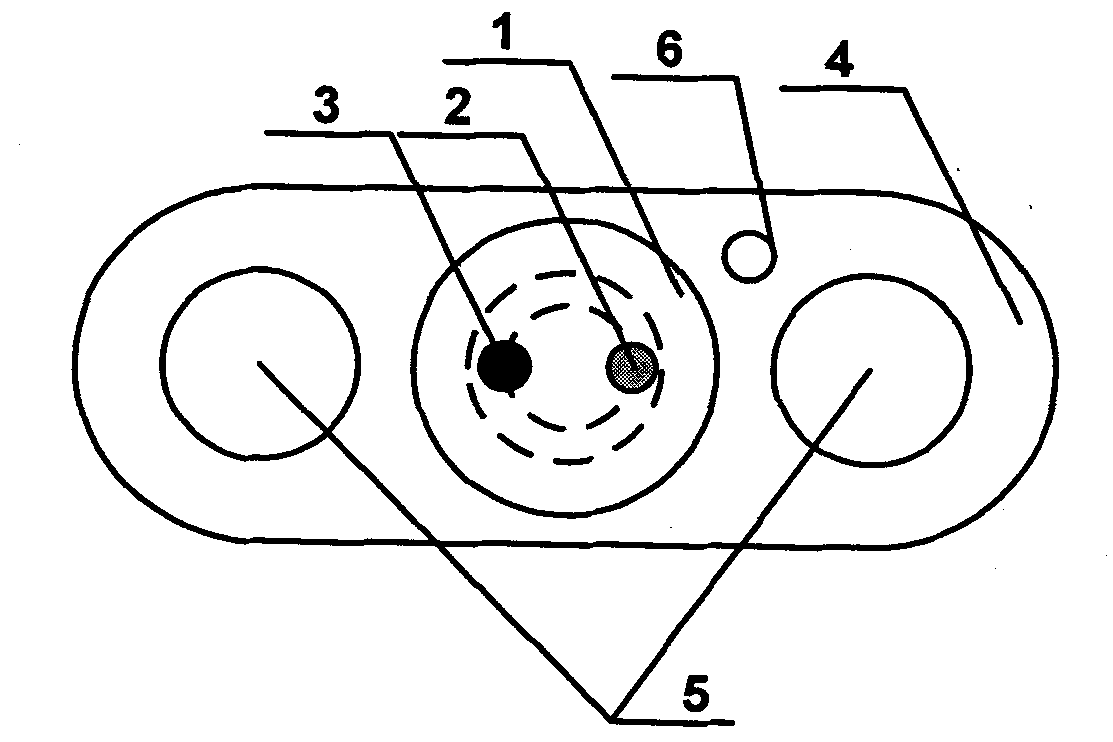
Figure 2 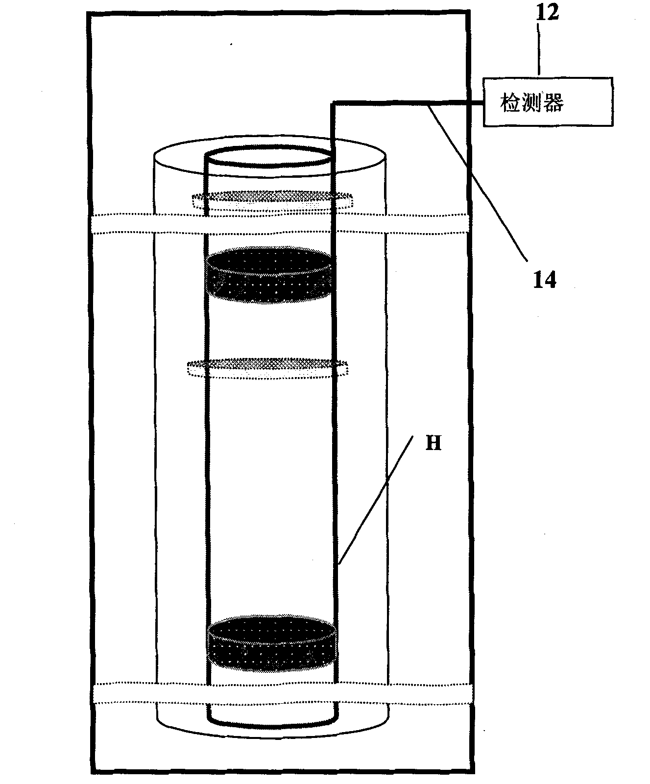
Figure 3
Abstract
Description
technical field
[0001] The invention relates to the technical field of laser monitoring, in particular to a temperature sensing system and a temperature monitoring method. Background technique
[0002] Wax removal is an important problem in oil field production. The reason is that the temperature under the formation is low. When the temperature is lower than the crystallization temperature of the wax, the wax will adhere to the pipe wall in solid form or be mixed in the oil, resulting in blockage of the pipe. , greatly reducing the efficiency of oil recovery. In order to solve this problem, for many years, pumping wells in Daqing Oilfield have mainly adopted wax removal methods such as thermal washing and wax removal, supplemented by sonic viscosity reduction devices, wax scraping rods, and solid wax preventers. At present, there are many problems in the oil field: low efficiency of thermal cleaning of oil wells, unknown advantages and disadvantages of thermal cleaning meth...
Examples
specific Embodiment approach 1
[0022] Specific implementation mode one: combine figure 1 Describe this embodiment, a distributed optical fiber sensing system based on Brillouin scattered light time domain reflection, which includes a laser 10, a coupler 11, a detector 12 and an optical fiber sensor 14, and the laser 10 outputs a beam to the coupler 11 Signal input end, the input / output end of described coupler 11 is connected with one end of optical fiber sensor 14, the optical signal output end of described coupler 11 is connected with the signal input end of detector 12, and the other end of optical fiber sensor 14 is arranged on The outer surface of the oil pipe H is laid in close contact with the oil pipe H.
specific Embodiment approach 2
[0023] Specific implementation mode two: combination figure 1 and figure 2 This embodiment is described. The difference between this embodiment and the first embodiment is the optical fiber sensor 14, which includes an oil-filled bundle tube 1, an optical fiber 2, and a PE sheath 4. The center of the PE sheath 4 is provided with an oil-filled The bundle tube 1 is provided with an optical fiber 2 at the center of the oil-filled bundle tube 1 , and the optical fiber 2 is arranged along the length direction of the oil-filled bundle tube 1 .
[0024] Oil-filled bundle tube 1 is the plastic tube that the inside is filled with fat-like ointment.
specific Embodiment approach 3
[0025] Specific implementation mode three: combination figure 1 and figure 2 This embodiment is described. The difference between this embodiment and the first or second embodiment is that the optical fiber sensor 14 also includes an FRP reinforcement 5 embedded in the PE sheath 4 and arranged symmetrically. On both sides of the oil-filled bundle tube 1.
[0026] Reinforcements made of fiber reinforced resin (FRP) are arranged on both sides of the oil-filled bundle tube 1 . The oil-filled bundle tube 1 and the FRP reinforcement are encapsulated together with a PE sheath 4 .