
VFTO measuring system

A measurement system and measurement device technology, applied in the field of VFTO measurement, can solve problems such as inability to meet measurement needs, and achieve the effect of expanding the measurement frequency band bandwidth

Active Publication Date: 2010-07-28
NORTH CHINA ELECTRIC POWER UNIV (BAODING) +1
View PDF3 Cites 23 Cited by
  • Summary
  • Abstract
  • Description
  • Claims
  • Application Information

AI Technical Summary

Problems solved by technology

Through research on the prior art, the inventor found that the equivalent frequency range of VFTO in GIS is from hundreds of kHz (kilohertz) to nearly a hundred MHZ (megahertz), and the above three methods are only applicable to a certain frequency band VFTO measurement, so there are different degrees of limitations in practical applications, which cannot meet the current measurement needs

Method used


Image

  • VFTO measuring system
  • VFTO measuring system
  • VFTO measuring system

Examples


Embodiment 1

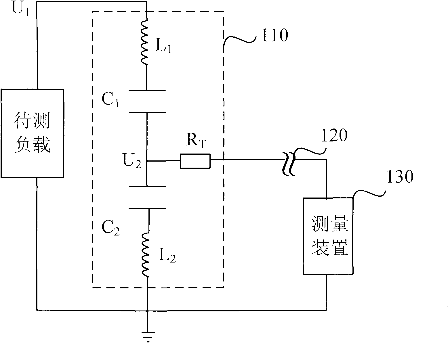
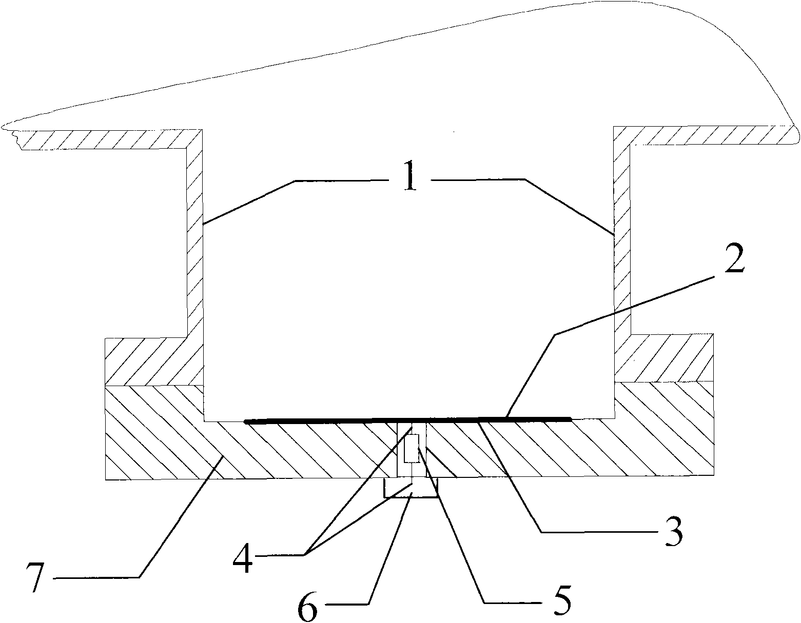
[0067] In the VFTO measurement system provided by the present invention, the voltage sensing device such as image 3 As shown, it includes: GIS shell hand window 1, coupling electrode 2, dielectric film 3, lead-out line 4, matching resistor 5, output interface 6 and hand window cover plate 7.

[0068] Wherein, the coupling electrode 2 is located inside the GIS housing hand window 1, the first side of the coupling electrode 2 faces the conductive rod in the GIS hand window, and the second side of the coupling electrode 2 faces the opening of the GIS hand window (that is, the direction facing the hand window cover plate 7 );

[0069] The dielectric film 3 is closely attached to the second side of the coupling electrode 2;

[0070] The hand window cover plate 7 is fixed on the GIS housing hand window 1, and the depth on the GIS hand window flange is adjustable, and there is an outlet hole in the middle of the hand window cover plate 7;

[0071] A matching resistor 5 is connecte...

Embodiment 2

[0074] Another voltage sensing device in the VFTO measurement system provided by the present invention is as Figure 4 As shown, it includes: GIS shell hand window 1, coupling electrode 2, dielectric film 3, lead-out line 4, matching resistor 5, output interface 6, first hand window cover 7a, second hand window cover 7b, first The sealing gasket 8a, the second sealing gasket 8b and the sealing medium plate 9.

[0075] In this embodiment, the hand window cover is composed of a first hand window cover 7a and a second hand window cover 7b, wherein the first hand window cover 7a is fixed to the GIS housing hand window 1, and the second The hand window cover 7b is embedded in the first hand window cover 7a, and the outlet hole is located on the second hand window cover 7b;

[0076] The sealing medium plate 9 is covered on the lead-out hole of the second hand window cover plate 7b, the first sealing gasket 8a is located between the first hand window cover plate 7a and the GIS housi...

Embodiment 3

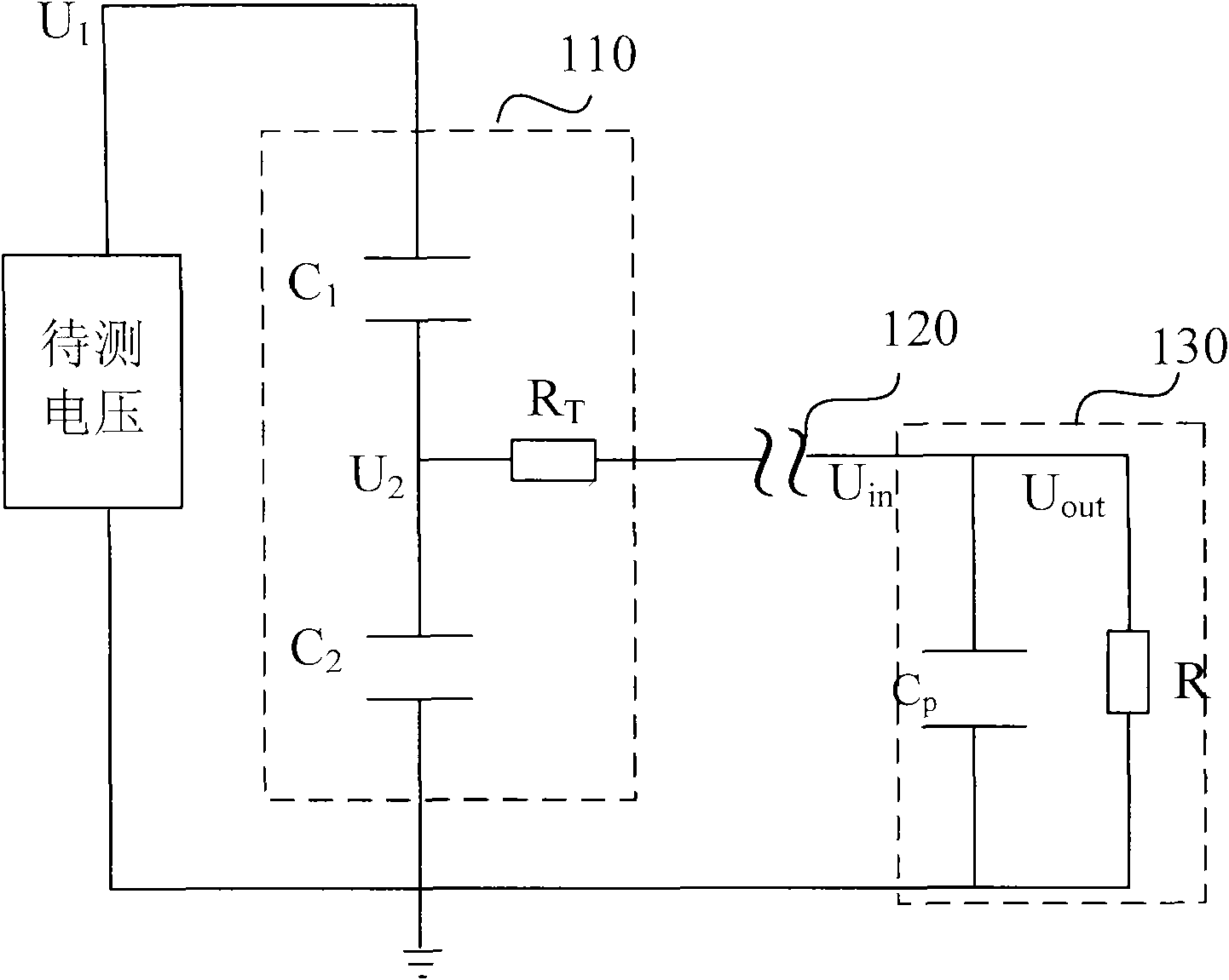
[0083] Apply the VFTO measurement system provided above to set up the voltage sensing device, the transmission device and the measuring device respectively.


PUM


Abstract

The application discloses a VFTO measuring system, comprising a voltage sensing unit, a transmission device and a measuring unit. The voltage sensing unit respectively forms a high voltage arm and a lower voltage arm featuring capacitance differential pressure with a load to be tested and a hand window cover plate to be tested by space electric field coupling and induces voltage of the load to betested; and the transmission device is connected between the voltage sensing unit and the measuring device for transmitting voltage the low voltage arm of the voltage sensing unit induces to the measuring device, wherein the voltage sensing unit comprises a GIS shell hand window, a coupling electrode, a medium film, an outgoing line, a build-out resistor, an output interface and a hand window cover plate. In the invention, with shape and area of the coupling electrode and distance of the coupling electrode from a conducting rod adjusted, with material and thickness of the medium film adjustedand with position of the outgoing line adjusted, measurement frequency band bandwidth can be expanded and VFTO measurement requirements can be met.

Description

technical field [0001] This application relates to the field of VFTO measurement, in particular to a VFTO measurement system. Background technique [0002] In GIS (Gas Insulated Switchgear, gas insulated substation), the operation of disconnectors, grounding switches and circuit breakers caused by the very fast transient process (Very Fast Transient) will have some adverse effects on the power system, especially the disconnector When it is suitable for the no-load bus, because of the relatively high probability and frequency of operation and the relatively long operation cycle, it will inevitably cause VFTO (Very Fast Transient Voltage, fast transient overvoltage) phenomenon. The equivalent frequency range of VFTO in GIS is hundreds of kHz (kilohertz) to nearly a hundred MHZ (megahertz), the rise time of VFTO can be as short as 4~7ns (nanoseconds), and the amplitude can reach up to 2.7 of the original voltage inside GIS. times. But for GIS, too high VFTO will not only caus...

Claims


Application Information

Patent Timeline
Patent Type & Authority Applications(China)
IPC IPC(8): G01R19/30
Inventor 李成榕孙岗陈国强张博徐海瑞吴昊
Owner NORTH CHINA ELECTRIC POWER UNIV (BAODING)
Learn More