Low-oxygen control system

A control system and control valve technology, which is applied in semiconductor/solid-state device manufacturing, electrical components, circuits, etc., can solve problems affecting the performance of microtransistors, and achieve the effect of reducing oxidation

Active Publication Date: 2010-07-28
BEIJING NAURA MICROELECTRONICS EQUIP CO LTD
View PDF0 Cites 15 Cited by
  • Summary
  • Abstract
  • Description
  • Claims
  • Application Information

AI Technical Summary

Problems solved by technology

The influence of the natural oxide layer brings challenges to the thin film process technology. For the thin film process, the change

Method used


Image

  • Low-oxygen control system
  • Low-oxygen control system

Examples


Embodiment Construction

[0024] The specific implementation manners of the present invention will be further described below in conjunction with the drawings and examples. The following examples are only used to illustrate the technical solution of the present invention more clearly, but not to limit the protection scope of the present invention.

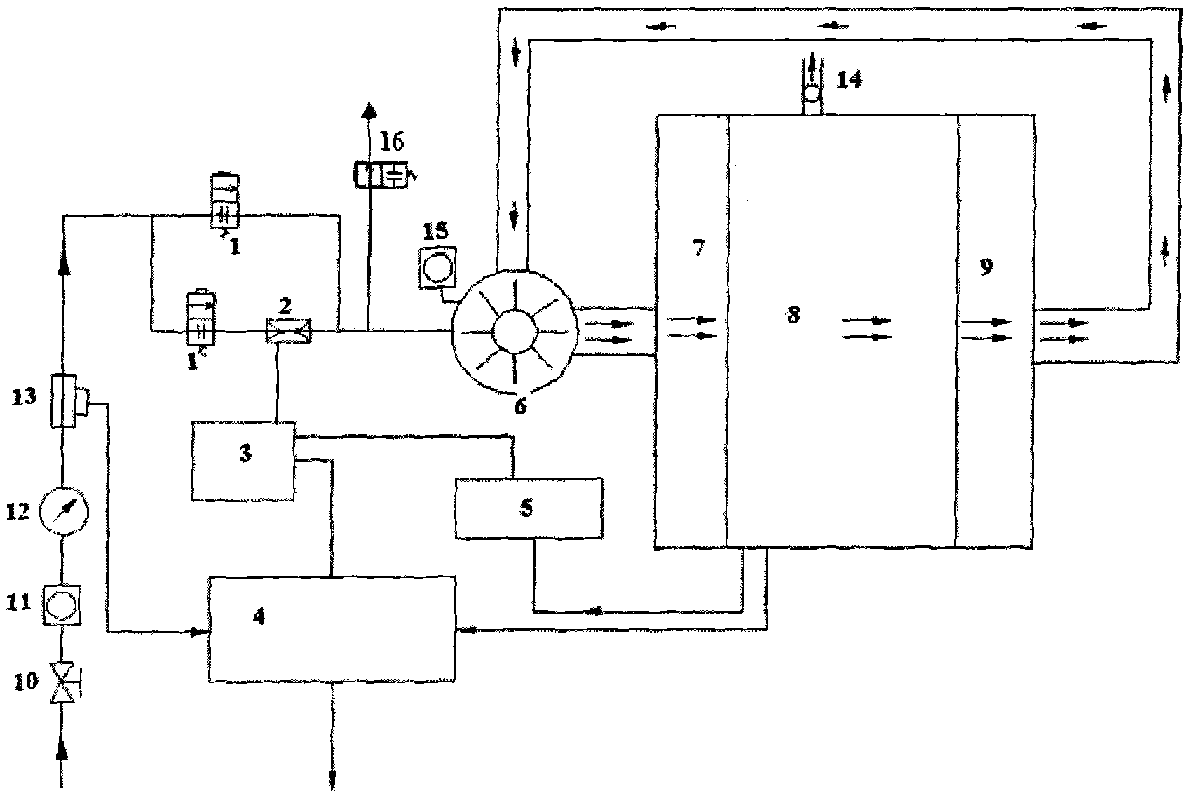
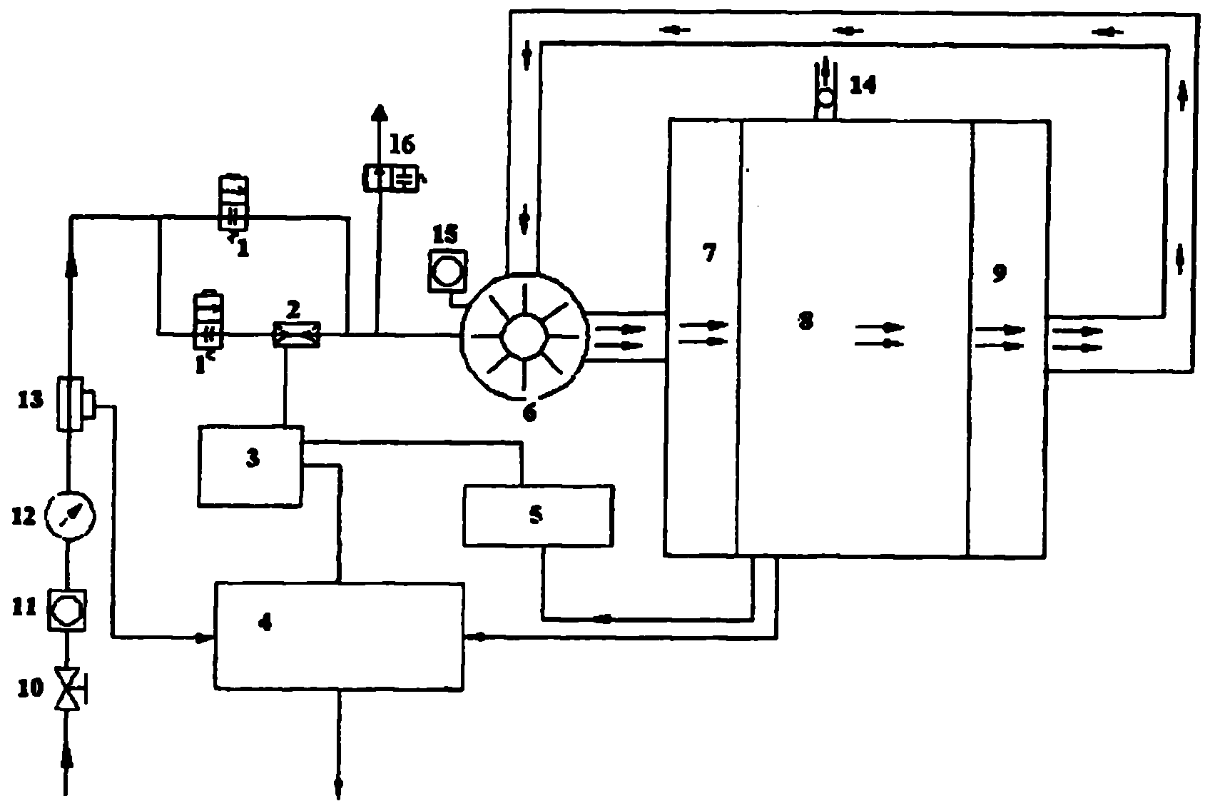
[0025] The microenvironment refers to the environment exposed to before and after the heat treatment of the wafer in the equipment, that is, the environment in which the wafer is picked up and oxidized in the processing chamber in the present invention. Preferably, the heat treatment of the wafer is carried out in a vertical heat treatment device. Hypoxia in the present invention means that the oxygen concentration is lower than 10ppm.

[0026] as attached figure 1 As shown, the hypoxic control system according to the specific embodiment of the invention includes a nitrogen delivery device, a circulation fan 6 and a processing chamber 8 connected in seque...


PUM


Abstract

The invention relates to the field of semiconductor production devices and discloses a low-oxygen control system comprising a nitrogen gas conveying device, a circulating fan and a treatment chamber which are connected in sequence, wherein the outside of the treatment chamber is also connected with a circulating pipe and an oxygen analyzer; the other inlet of the oxygen analyzer is connected with the nitrogen gas conveying device; and the circulating fan is also provided with an air ventilating valve. The low-oxygen control system can control the oxygen concentration of a relative space (microenvironment), thereby effectively controlling the natural oxygen condition of a chip.

Description

technical field [0001] The invention belongs to the field of semiconductor production devices, and in particular relates to a low-oxygen control system in a wafer oxidation process. Background technique [0002] In semiconductor production, it is often necessary to go through a heat treatment process. After heat treatment, a defect-free regional protective layer is formed on the near surface layer of the wafer. In the semiconductor manufacturing process, the goal of wafer heat treatment is to grow a defect-free and uniform film according to the thickness requirement. The so-called thin film is a thin solid substance grown on a substrate, which can be a conductor, an insulating substance or a semiconductor material. Thin films can be silicon dioxide (SiO 2 ), silicon nitride (Si 3 N 4 ) Polysilicon and metals, etc. [0003] SiO 2 It is an intrinsic (pure) glass body with a melting point temperature of 1732°C. thermally grown SiO 2 It can be tightly adhered to the sili...

Claims


Application Information

Patent Timeline
IPC IPC(8): H01L21/00
Inventor 林松赵星梅钟华
Owner BEIJING NAURA MICROELECTRONICS EQUIP CO LTD
Why Eureka
Try Eureka