Method and device for identifying an electronic code

An electronic code, code technology, applied in measuring devices, character and pattern recognition, record carriers used by machines, etc., to achieve considerable cost advantages, optimized electrical properties, and cost-effective effects

Inactive Publication Date: 2010-07-28
VALTION TEKNILLINEN TUTKIMUSKESKUS
View PDF5 Cites 0 Cited by
  • Summary
  • Abstract
  • Description
  • Claims
  • Application Information

AI Technical Summary

Problems solved by technology

So the question is using "digital technology" to assess the electrical correctness of lottery tickets

Method used


Image

  • Method and device for identifying an electronic code
  • Method and device for identifying an electronic code
  • Method and device for identifying an electronic code

Examples


Embodiment Construction

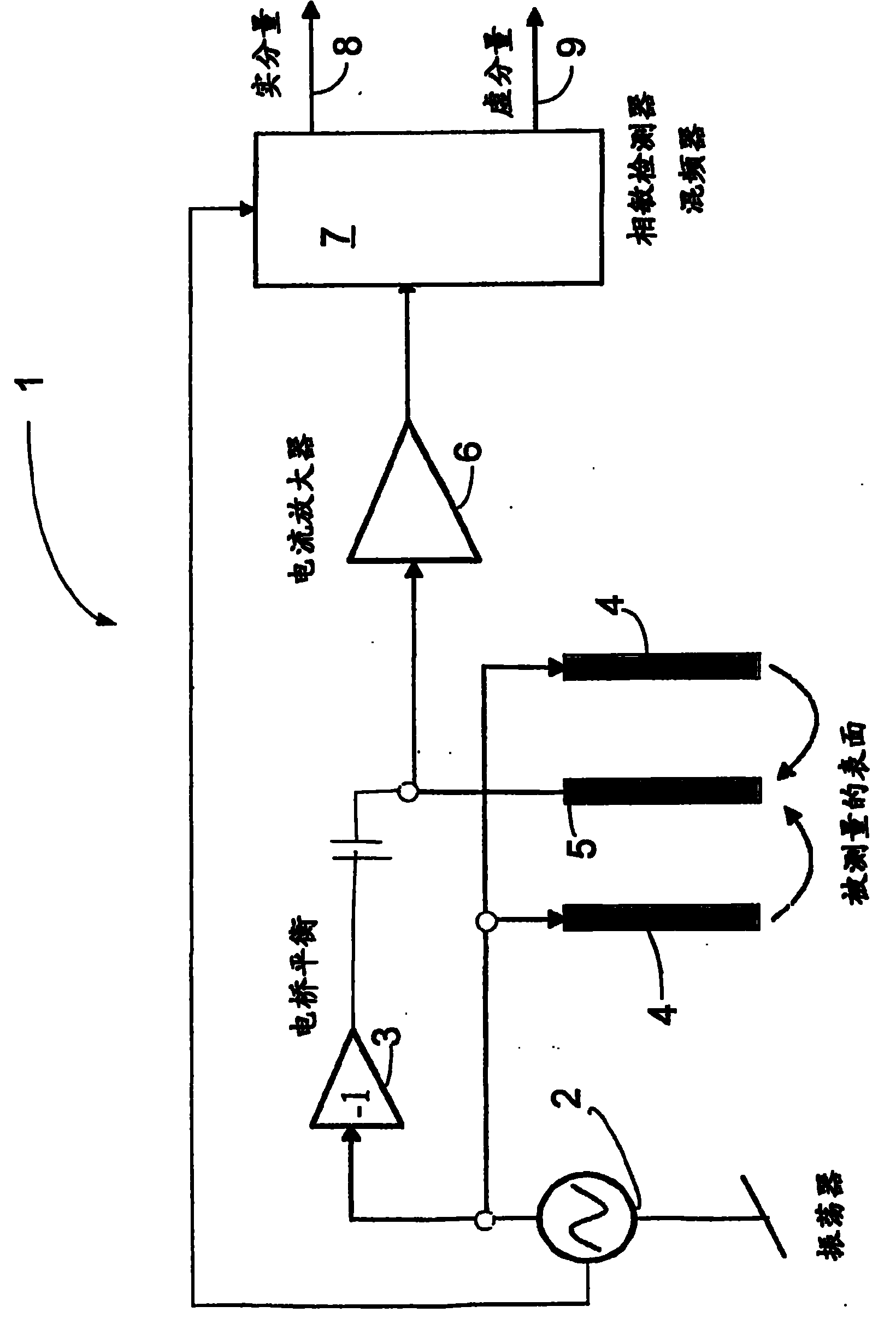
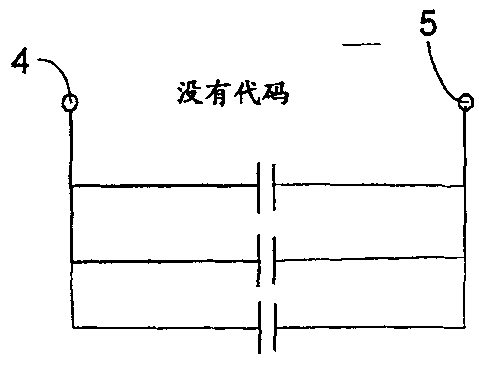
[0027] figure 1 Shown is a measuring device 1 in which two live electrodes 4 fed by an oscillator 2 excite a current through the surface to be measured and possibly through conductive structures present in the surface . In the arrangement according to the figure, the middle electrode 5 is used for the measurement signal. The wiring and the capacitance of the amplifier 6 (CMOS or JFET) are usually so large that the impedance of the read electrode 5 represents a capacitive short circuit. If this is not the case, the amplifier 6 is fed back with current, which makes the input impedance of the amplifier 6 very low. The signal is detected by using a phase sensitive detector 7 based on down mixing the signal with an alternating current connected in phase with the object, the phase of the signal is shifted by 90 degrees. If the measurement is not differential, in order to balance the bridge, an anti-phase signal is used to cancel out the capacitive connection between the conductor...


PUM


Abstract

The present publication discloses a method and device for reading an electronic code. According to the method, an alternating electrical signal is brought to the code (11) being measured, with the aid of electrodes (4, 5), and the current or voltage travelling through the electrodes (4, 5) is measured. According to the invention, the real (8) and the imaginary (9) components of the current or correspondingly the voltage are defined, and the electrodes (4, 5) being on an essentially lossless surface, an angle correction is made to the real (8) and imaginary (9) components of the current or the voltage, in such a way that substantial changes in the current take place only in the imaginary component (9) of the current or voltage.

Description

technical field [0001] The invention relates to a method for detecting an electronic code according to the preamble of claim 1 . [0002] The invention also relates to a plant intended for the method. Background technique [0003] According to the prior art, both optically readable barcodes and remotely readable RFID identifiers are used in the transportation of goods. [0004] The advantage of the barcode lies in its standardization technique, but this technique requires a visible mark and also requires a reading technique at least within a sight distance, which limits the range of applications. Visible markers make the technology vulnerable to abuse. [0005] RFID technology has many advantages over the aforementioned barcode technology, including long-range readability and the possibility of completely hiding the code in the product, which can be used to prevent counterfeiting of the code. However, the identifiers used in this technology are obviously much more expensi...

Claims


Application Information

Patent Timeline
Patent Type & Authority Applications(China)
IPC IPC(8): G06K7/08G06V30/224
CPCG06K19/067G01R27/02G06K7/081G07D7/02G11B9/04G11B9/06G06K7/08G06V30/224
Inventor H·塞帕H·西波拉A·劳蒂埃宁P·赫利斯托
Owner VALTION TEKNILLINEN TUTKIMUSKESKUS
Why Eureka
Try Eureka