Hydro-electric mixed driving system used for engineering machinery

A technology of hybrid drive and construction machinery, which is applied in the arrangement of multiple different prime movers of hybrid vehicles, motor vehicles, and general power units, etc. Unable to achieve normal operation and other problems, to achieve the effect of making full use of energy, improving operation reliability, and accelerating mechanism action

Inactive Publication Date: 2010-08-04
SHANGHAI SANY HEAVY IND
View PDF5 Cites 10 Cited by
  • Summary
  • Abstract
  • Description
  • Claims
  • Application Information

AI Technical Summary

Problems solved by technology

[0003] Among the driving methods of existing construction machinery, the use of hydraulic oil to drive hydraulic motors to realize the movement of mechanical actuators accounts for a large proportion. Its inherent disadvantages are: the inertia of construction machinery actuators is very large, and its braking is generally achieved by hydraulic pressure. The overflow of the motor is realized. During this process, the kinetic energy of the mechanism movement is lost in the form of heat energy. The lost energy is converted into the heat energy of the hydraulic oil. Under the condition of completing the same workload, the fuel consumption is more, and the heat dissipation is increased at the same time. System cooling burden
Although the hybrid power system has been successfully used in automobiles, if the system is directly applied to construction machinery, it will not be ab

Method used


Image

  • Hydro-electric mixed driving system used for engineering machinery
  • Hydro-electric mixed driving system used for engineering machinery
  • Hydro-electric mixed driving system used for engineering machinery

Examples


Embodiment 1

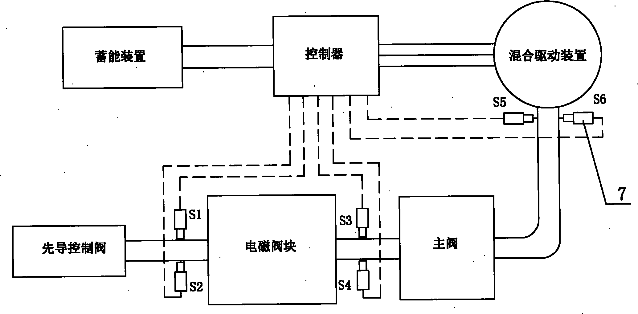
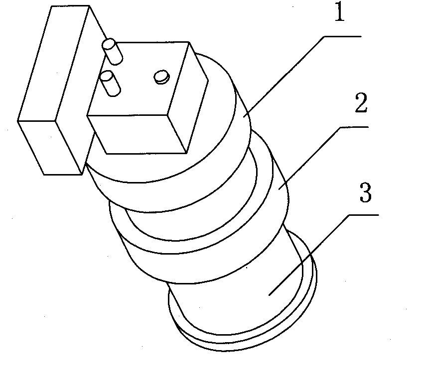
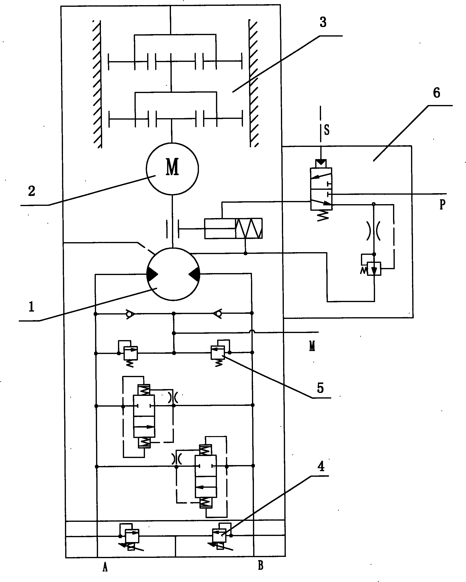
[0019] Embodiment one: see Figure 1~3 As shown, a hydraulic-electric hybrid drive system for engineering machinery includes a pilot control valve, a main valve, a power device and a controller, the output end of the power device is connected to the actuator, and the power device is a hybrid power device. It consists of a hydraulic motor 1, a motor generator 2 and a reducer 3 coaxially connected (such as image 3 shown).

[0020] In this embodiment, the actuator is a rotary platform on a hydraulic excavator, the moment of inertia of the platform is very large, and the braking of the platform is realized by the overflow of the hydraulic motor 1. During this process, the rotational kinetic energy of the platform is converted into thermal energy. Lost, this part of the energy lost in the past is converted into heat energy of the hydraulic oil, and the heat dissipation burden of the heat dissipation system is heavy, which leads to high energy consumption of the whole machine. Now...


PUM


Abstract

The invention discloses a hydro-electric mixed driving system used for engineering machinery, which comprises a pilot control valve, a main valve, a motive power device and a controller. The invention is characterized in that the motive power device is a mixed motive power device, and consists of a hydraulic motor, a motor generator and a speed reducing machine through coaxial connection, an electromagnetic overflow valve is respectively connected in parallel on the high-pressure oil output end of the hydraulic motor, the controller controls the motor generator, the electricity generation output of the motor generator is connected with an energy accumulator, the output end of the energy accumulator is connected with the electric input end of the motor generator, an electromagnetic valve block is arranged between the pilot control valve and the main valve, a pressure sensor is respectively arranged on the input and output end of the electromagnetic valve block and on a high-pressure oil inlet opening of the hydraulic motor, and each pressure signal is respectively input into the controller. The hydraulic motor and the motor generator of the invention are in coaxial connection, the braking overflow energy is recovered to be used as electric energy of the electric motor, the hydro-electric mixed driving on the engineering machinery is realized, the energy consumption of the wholemachine is lowered, and the use cost is saved.

Description

technical field [0001] The invention relates to a driving system for engineering machinery, in particular to a hydraulic-electric hybrid driving system for engineering machinery, which uses hydraulic motors and electric motors to drive the engineering machinery. Background technique [0002] In recent years, in view of the successful application in automobiles, the hybrid power system has been highly valued by various construction machinery enterprises, and has become one of the important research topics for construction machinery to save energy, reduce consumption and reduce emissions. In order to improve the competitiveness and market share of next-generation products, Hitachi Construction Machinery, Kobelco, Komatsu, Caterpillar and other major construction machinery manufacturers in the world have carried out research work on the application of hybrid power systems in the field of construction machinery. [0003] Among the driving methods of existing construction machine...

Claims


Application Information

Patent Timeline
IPC IPC(8): B60K6/22B60W20/00
Inventor 戴晴华易迪升蒲金鹏龙也
Owner SHANGHAI SANY HEAVY IND
Why Eureka
Try Eureka