
Method and machine for calcining materials

A material and calcination technology, which is applied in the field of methods and assembled machinery, can solve the problems of increasing equipment investment and operating costs, uneven heating of limestone, and large stone gas resistance, so as to reduce equipment investment and operating costs, and is conducive to environmental protection , full exposure to the effect

Active Publication Date: 2010-08-04
SHIJIAZHUANG XINHUA IND FURNACE CO LTD
View PDF6 Cites 7 Cited by
  • Summary
  • Abstract
  • Description
  • Claims
  • Application Information

AI Technical Summary

Problems solved by technology

The disadvantage of this process is that the direction of the furnace gas flow in the shaft kiln is opposite to that of the stone material, that is, the stone material moves from top to bottom, and the furnace gas flows from bottom to top. Gas segregation phenomenon causes uneven heating of limestone and affects product quality
However, this patent application requires the indirect use of waste heat through the heat exchange of the regenerator in the regenerator, which increases equipment investment and operating costs on the one hand, and increases exhaust gas emissions on the other hand, which is not conducive to environmental protection.

Method used


Image

  • Method and machine for calcining materials
  • Method and machine for calcining materials
  • Method and machine for calcining materials

Examples


Embodiment Construction

[0018] The present invention will be further described below in conjunction with the accompanying drawings.

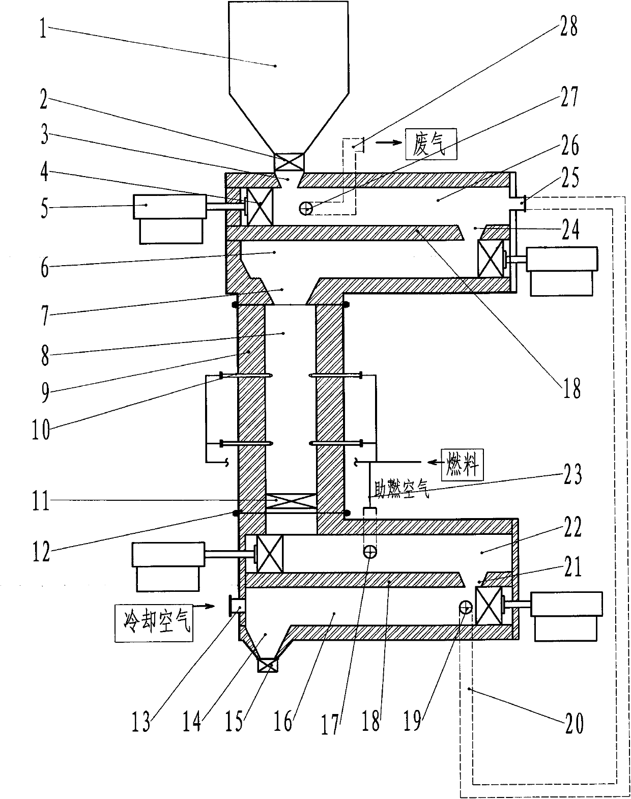
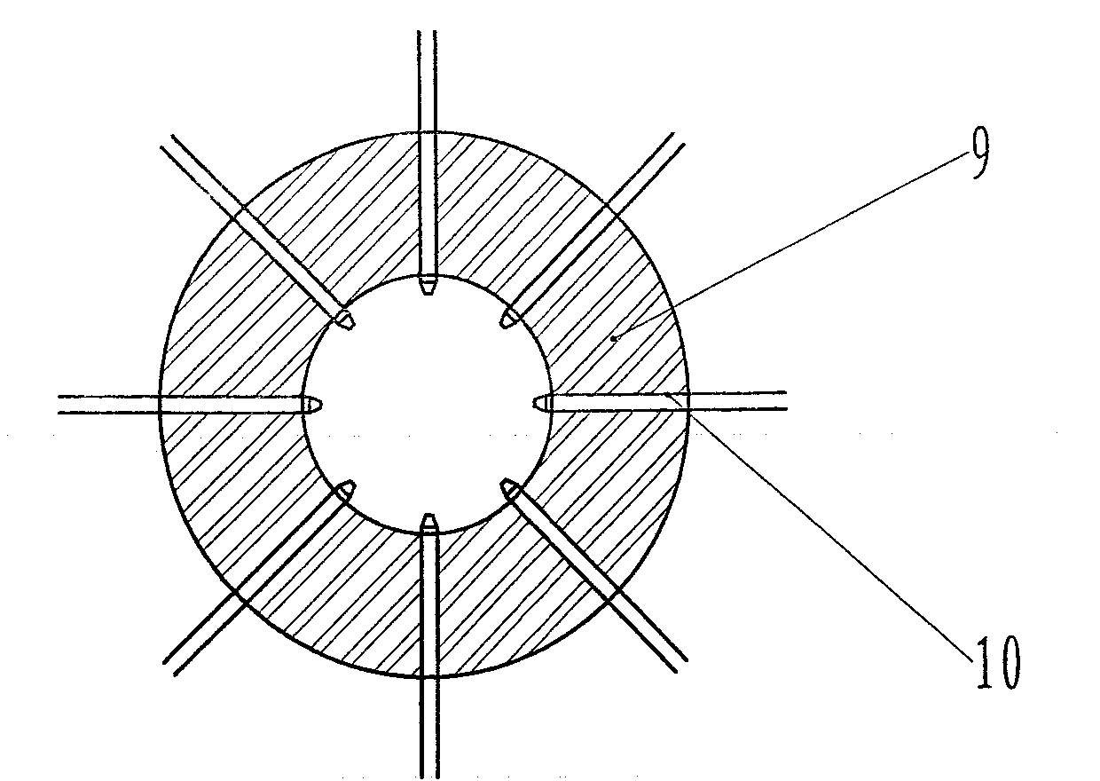
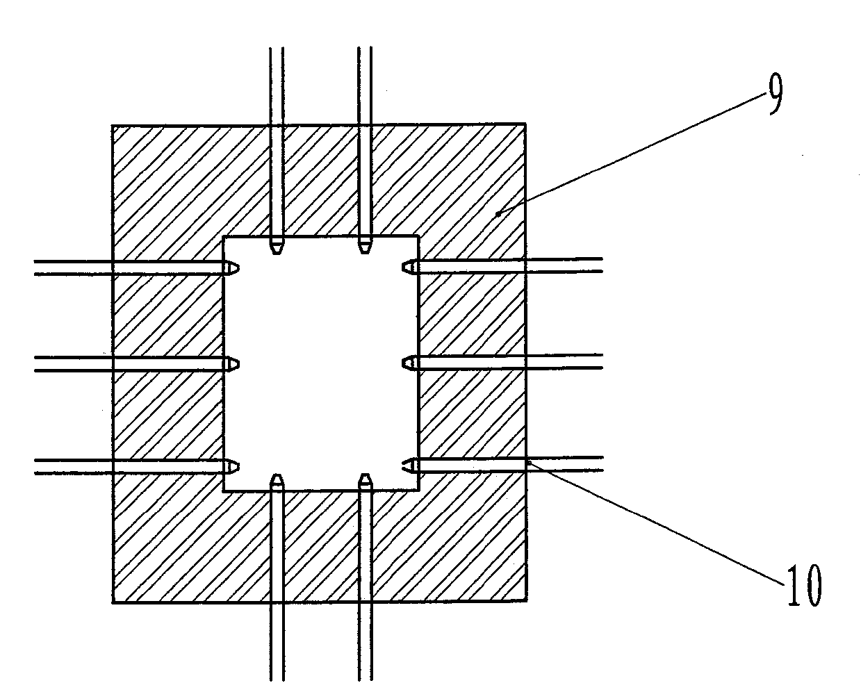
[0019] The machinery of calcined material of the present invention is as figure 1 As shown, it consists of feeding equipment, preheating chamber, calcining chamber, cooling chamber, discharging equipment and exhaust gas discharge system. The feeding equipment includes hopper 1, feeding lock 2, material conveying equipment and matching control system. The calciner is provided with two rows of peripheral burners 10, the burners are gas fuel burners, and a discharge lock 11 is provided between the calciner and the high-temperature cooling chamber. The preheating chamber and the cooling chamber are arranged horizontally. The middle of the preheating chamber is divided into a high temperature preheating chamber 6 and a low temperature preheating chamber 26 by a partition wall 18. The low temperature preheating chamber is located in the upper part, the high temperature preh...


PUM


Abstract

The invention provides a method and a machine for calcining materials, comprising feeding equipment, a preheating chamber, a calcining chamber, a cooling chamber, discharging equipment and an exhaust emission system, wherein the calcining chamber is provided with 1-10 rows of peripheral burners, and the preheating chamber and the cooling chamber are transversely arranged. The preheating chamber and the cooling chamber are respectively divided into a high-temperature preheating chamber and a low-temperature preheating chamber as well as a high-temperature cooling chamber and a low-temperature cooling chamber by partition walls. The materials of the preheating chamber and the cooling chamber transversely move under the push of a pusher; higher-temperature air after the high-temperature cooling chamber cools products is used as combustion air; higher-temperature air after the low-temperature cooling chamber cools the products is used for preheating limestone materials in the preheating chamber. In the invention, heat energy is well utilized to save heat-exchange equipment and reduce equipment investments and operating costs, which reduces the discharge of greenhouse gases and is beneficial to environmental protection. The machinery is a detachable assembly, and all component equipment is manufactured separately and is assembled on site, thereby facilitating transportation, installation, overhauling and replacement and being beneficial to serialized production of calcining machinery.

Description

technical field [0001] The invention relates to a method and equipment for calcining materials, in particular to a method and an assembled machine for making full use of the high-temperature air after cooling lime as combustion-supporting air and preheating the materials to be processed. Background technique [0002] Lime is an important building material, and also an important raw material in metallurgy and chemical industry. The prior art uses dolomite and limestone as raw materials, and adopts a vertical kiln with burning beams to calcinate lime. The disadvantage of this process is that the direction of the furnace gas flow in the shaft kiln is opposite to that of the stone material, that is, the stone material moves from top to bottom, and the furnace gas flows from bottom to top. Gas segregation phenomenon causes limestone to be heated unevenly and affects product quality. The applicant disclosed a utility model patent with the patent number ZL200320111077.3 for an int...

Claims


Application Information

Patent Timeline
IPC IPC(8): C04B2/12
Inventor 贾会平
Owner SHIJIAZHUANG XINHUA IND FURNACE CO LTD
Learn More