
Light spot position detection device, optical component and electronic equipment

A technology of detection device and light spot, which is applied in the direction of measuring device, measuring distance, line-of-sight measurement, etc., can solve the problems of unfixed ranging period, difficult to use, and difficult to use miniaturization of signal processing, etc., to achieve the effect of reducing power consumption

Active Publication Date: 2010-08-04
SHARP KK
View PDF2 Cites 7 Cited by
  • Summary
  • Abstract
  • Description
  • Claims
  • Application Information

AI Technical Summary

Problems solved by technology

[0012] First, in the case of the distance measuring device disclosed in Patent Document 1, the output current i from the PSD 4 is changed according to the measurement environment. 1 i 2 Therefore, the short-distance measurement can be performed relatively early. In contrast, the long-distance measurement takes time, so the distance measurement period is not fixed, and it is very difficult to use for the subsequent equipment that obtains the distance measurement value.
[0013] In addition, there is a problem that it is difficult to achieve miniaturization as described above by using the signal processing using the above-mentioned PSD4.
[0014] In addition, when the distance measuring device disclosed in the above-mentioned Patent Document 1 is applied to a solid-state imaging device, since the amount of reflected light emitted from the IRED3 and reflected on the object is small, it may be difficult to mount a device that acquires the device together with ambient light. The reflected light of IRED3 is an analog circuit that only extracts the above reflected light, and there is a problem of lack of resistance to ambient light
[0015] Next, in the case of the distance measuring device for a camera disclosed in the above-mentioned Patent Document 2, the environmental light resistance is improved by using a solid-state imaging element as the light receiving element 10, but there is a problem that it is difficult to measure distances from short distances to long distances by using reflected light. problem of distance

Method used


Image

  • Light spot position detection device, optical component and electronic equipment
  • Light spot position detection device, optical component and electronic equipment
  • Light spot position detection device, optical component and electronic equipment

Examples


no. 1 Embodiment approach

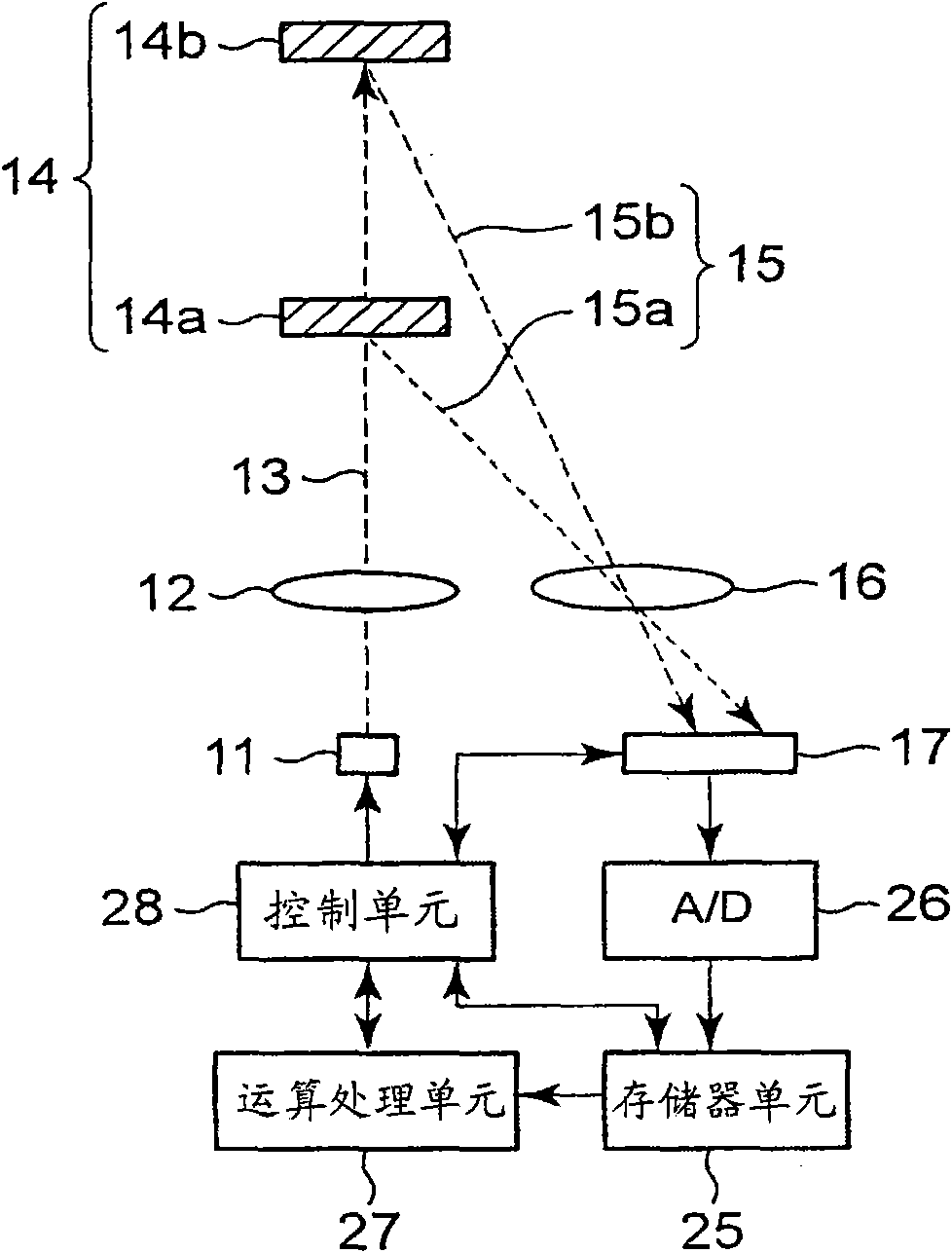
[0119] figure 1 It is a schematic configuration diagram in a case where the light spot position detection device of this embodiment is applied to an optical distance measuring device by triangulation. exist figure 1 Here, light emitted from a light emitting element 11 that is an LED (Light Emitting Diode) or an LD (Laser Diode) is condensed by a projection mirror 12 to become an outgoing light beam 13 , and is diffusely reflected on an object 14 to be measured. The reflected beam 15 of the reflected light is condensed by the condenser lens 16 to form a spot image on the solid-state imaging device 17 . In addition, 14a represents a short-distance measurement object, and 14b represents a long-distance measurement object. In addition, 15a denotes a reflected beam reflected by the short-distance measurement object 14a, and 15b denotes a reflected beam 15b reflected by the long-distance measurement object 14b.

[0120] according to figure 1 It can be seen that the light spot...

no. 2 Embodiment approach

[0166] In this embodiment, as in the case of the above-mentioned first embodiment, the light spot position detection device is applied to figure 1 The case of the reflective optical distance measuring device shown will be described as an example. In addition, the structure of the optical distance measuring device is the same as figure 1 The optical distance measuring device shown is the same, and the following description also uses figure 1 to proceed.

[0167] 17( a ) and ( b ) are diagrams for explaining the exposure method for the pixel unit 31 in the solid-state imaging device 17 according to this embodiment. also, Figure 18(a)-18(d) It shows the operation timing chart of the optical distance measuring device equipped with this light spot position detection device.

[0168] In the above-mentioned first embodiment, the signal light including ambient light emitted from the light-emitting element 11 and reflected on the object 14 to be measured, and only the ambient l...


PUM


Abstract

The present invention relates to a light spot position detection device, an optical component comprising the device and electronic equipment comprising the optical component. In a light spot position detection device, in one frame of operation, under control of a control unit, pixel data obtained in a pixel section in exposure of a solid-state image sensor in synchronization with light emission of a light emitting element are added to corresponding storage portions in a memory unit, and pixel data obtained in exposure of the image sensor asynchronous to the light emission of the light emitting element are subtracted from the corresponding storage portions, to store pixel data of only signal light in the storage portions. A given number of frames of operation are repetitively performed toaccumulate pixel data of only the signal light in the storage portions. The position of a light spot on the pixel section is calculated based on the pixel data of only the signal light and outputted whether the storage portions are saturated or not with the pixel data.

Description

technical field [0001] The present invention relates to a light spot position detection device for detecting the position of a light spot formed on a solid-state imaging element by an optical system, an optical component including the same, and an electronic device including the optical component. Background technique [0002] An optical distance measuring device is representative of a device equipped with a light spot position detection device that detects the position of a light spot formed on the solid-state imaging element by an optical system on the solid-state imaging element. The measurement principle of this optical distance measuring device generally utilizes known triangulation distance measurement, and detects the above-mentioned The position of the light-receiving point on the solid-state imaging element is used to calculate the distance to the above-mentioned measurement object. [0003] As such an optical distance measuring device, there is a distance measurin...

Claims


Application Information

Patent Timeline
Patent Type & Authority Applications(China)
IPC IPC(8): G01S17/06G01S3/784G01S17/48
CPCG01S7/4868G01S17/48
Inventor 和田秀夫
Owner SHARP KK
Learn More