Light emitting diode package and projecting device

A technology of light-emitting diodes and projection devices, applied in projection devices, optics, installation, etc., can solve the problems of reduced yield, long alignment hours, and large alignment errors, and achieve simplified structure, easy assembly, and accurate alignment Effect

Inactive Publication Date: 2010-08-04
YOUNG OPTICS
View PDF0 Cites 5 Cited by
  • Summary
  • Abstract
  • Description
  • Claims
  • Application Information

AI Technical Summary

Problems solved by technology

[0004] However, since the size of the light-emitting diode chip is smaller than that of other light-emitting elements such as ultra high pressure lamp (UHP lamp), the volume of the light integrating column suitable for the light-emitting diode chip must also be reduced accordingly, which will Difficulty aligning the light integrating column with the light-emitting diode chip, resulting in excessive alignment errors and long alignment hours
Furthermore, excessive alignment errors will result in a drop in the yield rate, and excessively long alignment hours will be unfavorable for mass production.

Method used


Image

  • Light emitting diode package and projecting device
  • Light emitting diode package and projecting device
  • Light emitting diode package and projecting device

Examples


Embodiment Construction

[0042] The following descriptions of various embodiments refer to the accompanying drawings to illustrate specific embodiments in which the present invention can be practiced. The direction terms mentioned in the present invention, such as "up", "down", "front", "rear", "left", "right", etc., are only referring to the directions of the drawings. Accordingly, the directional terms are used to illustrate, not to limit, the invention.

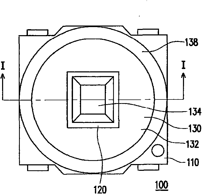
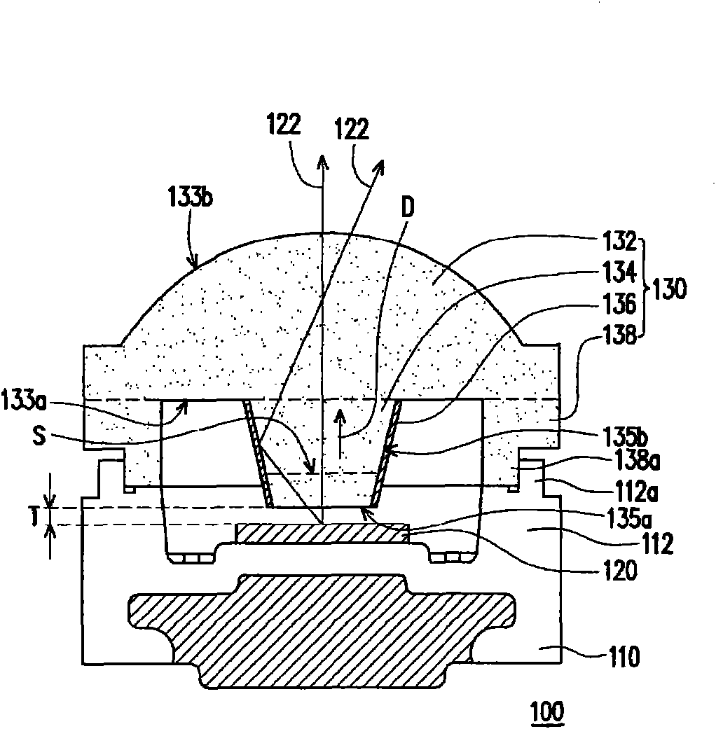
[0043] Figure 1A It is a schematic top view of a light emitting diode package according to an embodiment of the present invention, and Figure 1B for Figure 1A A schematic cross-sectional view of the light emitting diode package along the line I-I. Please refer to Figure 1A and Figure 1B , the light emitting diode package 100 of this embodiment includes a carrier 110 , a light emitting diode chip 120 and a light guide element 130 . In this embodiment, the carrier 110 is, for example, a lead frame. However, in other embodiments, the carrier...


PUM


Abstract

The invention relates to a light emitting diode package which comprises a loader, at least one light emitting diode chip and a light guide element, wherein the light emitting diode chip is arranged on the loader; the light guide element is also arranged on the loader above the light emitting diode chip and comprises a transparent body, a light integration part, a reflecting film and a supporting part; the light integration part is connected to the transparent body between the transparent body and the light emitting diode chip and provided with a light inlet surface and at least one side surface; the light inlet surface faces towards the light emitting diode chip, and the side surfaces are connected with the transparent body and the light inlet surface; the reflecting film is arranged on the side surfaces; the supporting part is connected to the transparent body and surrounds the light integration part; the supporting part supports and leans against the loader; and the transparent body, the light integration part and the supporting part are integrally molded. The invention also provides a projecting device.

Description

technical field [0001] The present invention relates to a light source and a display device, and in particular to a light emitting diode package (LED package) and a projection apparatus. Background technique [0002] In recent years, due to the continuous improvement of the luminous efficiency of light-emitting diodes, light-emitting diodes have gradually replaced traditional light sources in many fields. Since the light emitting phenomenon of the light emitting diode is not by heating or discharging, but belongs to cold light, the life of the light emitting diode is more than 100,000 hours. In addition, light-emitting diodes have the advantages of fast response (about 10-9 seconds), small size, low power consumption, low pollution, high reliability, and suitable for mass production. Therefore, light-emitting diodes can be used in a wide range of fields. [0003] Generally speaking, the light intensity of the light emitted by the LED chip exhibits a lambertian intensity dis...

Claims


Application Information

Patent Timeline
Patent Type & Authority Applications(China)
IPC IPC(8): H01L25/075H01L33/00G02B6/00G02B7/00G03B21/14
Inventor 陈美玲温文杰潘浩炜陈昭舜
Owner YOUNG OPTICS
Why Eureka
Try Eureka