Electromagnetic wave welding method and device for solar cells

A technology for solar cells and welding devices, applied in high-frequency current welding equipment, welding equipment, circuits, etc., can solve the problems of high energy consumption, broken cells, and low production efficiency.

Inactive Publication Date: 2010-08-11
SUZHOU SUOLIWANG NEW ENERGY TECH CO LTD
View PDF6 Cites 19 Cited by
  • Summary
  • Abstract
  • Description
  • Claims
  • Application Information

AI Technical Summary

Problems solved by technology

[0002] In the manufacturing process of crystalline silicon solar cell components, cells must be welded into strings. The welding of cells and cell strings has a key impact on the production efficiency and quality stability of crystalline silicon solar cell components. The current crystalline silicon solar cells There are two methods of welding for chips and cell strings. The first is manual welding. Electric soldering iron is usually used for manual welding, which has low production efficiency and poor quality stability; the second is welding by a fully automatic welding machine. , the welding of the automatic welding ma...

Method used


Image

  • Electromagnetic wave welding method and device for solar cells
  • Electromagnetic wave welding method and device for solar cells
  • Electromagnetic wave welding method and device for solar cells

Examples


Embodiment Construction

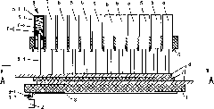
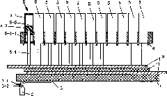
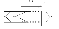
[0025] Such as figure 1 , 3 , 4, 5, and 6, an electromagnetic wave welding method for solar cells, comprising the following steps: superimposing solar cells 7 and welding ribbons 8 on a non-magnetic workbench 1, so that the welding ribbons 8 and solar cells The main grid line of the sheet 7 is in contact with each other, and the elastic pressing device 5 is used to press the welding ribbon 8 and the battery sheet 7, and the high-frequency power supply 2 is used to supply power to the two copper tube induction coils 3 arranged under the surface of the workbench 1. The tube induction coil 3 is in a "U" shape, and the copper tube induction coil 3 is cooled by the cooling medium 4 flowing inside, and the high-frequency oscillating electromagnetic waves generated by the copper tube induction coil 3 make the main grid lines of the welding strip 8 and the battery sheet 7 Both generate eddy current and generate heat, so that the welding ribbon 8 and the main grid line of the battery ...


PUM

PropertyMeasurementUnit
Frequency rangeaaaaaaaaaa

Abstract

The invention discloses an electromagnetic valve welding method and an electromagnetic valve welding for solar cells. The method comprises the following steps of: superposing the solar cells and welding strips on a non-magnetic workbench and allowing the welding strips to contact bus bars of the solar cells; pressing the welding strips and the cells together by using an elastic pressing device; supplying power to a copper pipe induction coil, which is arranged below the workbench surface, by using a high-frequency power supply, wherein the copper pipe induction coil is 'u'-shaped; allowing a cooling medium which flows in the inner part of the copper pipe induction coil to cool the copper pipe induction coil; uniformly heating the welding strips and the bus bars of the panels with high-frequency oscillation electromagnetic waves generated by the copper pipe induction coil; and welding the welding strips and the bus bars of the panels together. The device comprises the workbench, the elastic pressing device and the high-frequency power supply, wherein the elastic pressing device is arranged above the workbench; the high-frequency power supply is connected with the copper pipe induction coil; and the copper pipe induction ring is 'u'-shaped and fixed below the workbench surface. The electromagnetic valve welding method and the electromagnetic valve welding for the solar cells have the advantages of high heating speed, high production efficiency, simple structure, uniform magnetic field and high welding quality.

Description

technical field [0001] The invention relates to a high-frequency electromagnetic wave welding method and device for solar cells, which are used in the solar cell component manufacturing process, and are especially suitable for the cell string welding method and device. Background technique [0002] In the manufacturing process of crystalline silicon solar cell components, cells must be welded into strings. The welding of cells and cell strings has a key impact on the production efficiency and quality stability of crystalline silicon solar cell components. The current crystalline silicon solar cells There are two methods of welding for chips and cell strings. The first is manual welding. Electric soldering iron is usually used for manual welding, which has low production efficiency and poor quality stability; the second is welding by a fully automatic welding machine. , The welding of the automatic welding machine mainly uses infrared heating welding, the welding speed is slo...

Claims


Application Information

Patent Timeline
IPC IPC(8): B23K13/01H01L31/18
CPCY02P70/50
Inventor 朱灯林卞新高杨泽民梅志千李新宏
Owner SUZHOU SUOLIWANG NEW ENERGY TECH CO LTD
Why Eureka
Try Eureka