
Heavy-draft truss upright-column combined platform

A water truss and combined technology, which is applied to the field of deep draft truss and column combined platforms, can solve the problems of difficult design, poor heave motion performance, and small area of ​​the upper deck, so as to improve the ability to adapt to harsh marine environments, improve the Overall structural stiffness and strength, effect of reducing surface wave loads

Active Publication Date: 2010-08-11
CHINA NAT OFFSHORE OIL CORP +1
View PDF6 Cites 18 Cited by
  • Summary
  • Abstract
  • Description
  • Claims
  • Application Information

AI Technical Summary

Problems solved by technology

Each of the above-mentioned platforms has its advantages and disadvantages: semi-submersible platforms have poor heave motion performance, and wet-type trees must be used as deep-water oil and gas development and production platforms, and wet-type trees are complex in technology and expensive; The post platform has good motion performance and can be used with a dry Christmas tree, but it has the disadvantages of small upper deck area, difficult design, and difficult layout of oil and gas treatment facilities; the tension leg platform also has good motion performance, but due to its use The tension leg is connected to the seabed foundation, and its cost increases rapidly with the increase of water depth

Method used


Image

  • Heavy-draft truss upright-column combined platform
  • Heavy-draft truss upright-column combined platform
  • Heavy-draft truss upright-column combined platform

Examples


Embodiment Construction

[0016] The present invention will be described in detail below in conjunction with the accompanying drawings and embodiments.

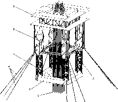
[0017] Such as figure 1 As shown, the present invention comprises a square or approximately square annular ballast tank 1, four vertical columns 2 positioned at corners of the annular ballast tank 1, four buoyant tank structures 3 positioned at the middle of the column 2 and a The drilling rig and the oil and gas processing module 4 located on the top of the column 2.

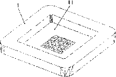
[0018] Such as figure 2 As shown, the annular ballast tank 1 adopts a permanent fixed ballast method, and the tank is filled with iron ore or other heavy objects to ensure that the buoyancy center of the platform is higher than the center of gravity at any time, so that the platform maintains a relatively deep draft during service , which not only realizes the unconditional stability of the platform in the marine environment, but also ensures that the stability and seakeeping of the...


PUM


Abstract

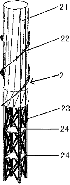
The invention relates to a heavy-draft truss upright-column combined platform which is characterized by comprising a regular-polygon or subregular-polygon annular ballast compartment, a plurality of vertical upright columns, a drilling machine and an oil gas processing module, wherein the vertical upright columns are positioned at the angular points of the annular ballast compartment, and the drilling machine is positioned on the top of the upright columns; the annular ballast compartment adopts a permanent ballast mode, and a weight is filled in the compartment, thereby ensuring that the center of buoyancy of the platform is higher than the center of gravity of the platform; the lower parts of upright columns are connected with the annular ballast compartment to form an integral body, the upper part of each upright column is in a cylinder or subterete shell structure, the lower part of the upright columns adopts a truss structure, and the middle parts of every two adjacent upright columns are connected through a buoyancy tank structure which can provides sufficient buoyancy force for the platform; and each upright column is provided with a set of berthing ropes, and the berthing ropes are connected to benthonic anchor points in a traditional anchoring mode. The invention has the advantages of favorable moving performance, wide applicability for operating water depth, high strength of the monolithic construction, light weight and low construction cost, and can be used for deep water oil gas exploitation in severe marine environments.

Description

technical field [0001] The invention relates to a floating oil production platform, in particular to a deep-draft truss-column combined platform with unconditional stability for deep-water offshore oil and gas development. Background technique [0002] With the development of offshore oil and gas moving into deep water, the traditional fixed oil production platform can no longer meet the needs of offshore deep water oil and gas development, and the floating oil production platform has become the main equipment for offshore deep water oil and gas development. In recent years, a variety of floating oil production platforms for offshore deepwater oil and gas development have been produced, which are widely used in the development of deepwater oil and gas fields around the world, such as semi-submersible platforms, deep-draft single-column platforms and tension leg platforms. Each of the above-mentioned platforms has its advantages and disadvantages: semi-submersible platforms h...

Claims


Application Information

Patent Timeline
IPC IPC(8): E02B17/00
CPCB63B43/06B63B35/4413B63B39/005B63B1/107B63B2001/128
Inventor 谢彬谢文会曾恒一张威王俊荣
Owner CHINA NAT OFFSHORE OIL CORP
Learn More