
Method for improving recovery ratio of thick-layer massive thickened oil by utilizing subsection fireflooding exploitation

A recovery factor and fire-flooding technology, which is applied in the fields of fluid production, earth-moving drilling, wellbore/well components, etc., can solve the problems of increasing difficulty of oil-layer fire-excavation, increase the fire-swept volume, improve the development effect, Targeted effect

Active Publication Date: 2013-06-05
PETROCHINA CO LTD
View PDF3 Cites 0 Cited by
  • Summary
  • Abstract
  • Description
  • Claims
  • Application Information

AI Technical Summary

Problems solved by technology

In addition, considering the distribution of interlayers in layers, the difficulty of burning oil layers increases with the increase of reservoir thickness.

Method used


Image

  • Method for improving recovery ratio of thick-layer massive thickened oil by utilizing subsection fireflooding exploitation
  • Method for improving recovery ratio of thick-layer massive thickened oil by utilizing subsection fireflooding exploitation
  • Method for improving recovery ratio of thick-layer massive thickened oil by utilizing subsection fireflooding exploitation

Examples


Embodiment 1

[0084] Oilfield 1 is a monocline oil reservoir bounded by faults on three sides. The buried depth of the oilfield is -1540~-1890m, the effective thickness of the oil layer is 103.8m, and the internal barrier is not developed. It is a thick massive oil reservoir with an average porosity of 0.212 and an average permeability of 1376md. At present, the average remaining oil saturation is about 0.55.

[0085] 1) Carry out rough screening according to the geological characteristics and development status of the oilfield. The reservoir meets the following conditions: oil layer thickness > 30m, single layer thickness > 10m, remaining oil saturation > 0.45, porosity > 0.18, permeability > 200md, degassed crude oil viscosity < 10000mPa.s under formation conditions, oil layer depth < 2000m;

[0086] 2) The research results of the production split based on the heating volume coefficient of the oil well show that the current recovery degrees of the upper and lower layers are 16.77% and 5...

Embodiment 2

[0089] The buried depth of oilfield 2 is -1510~-1690m, the effective thickness of the oil layer is 83m, and the internal barrier is not developed. It is a thick massive oil reservoir with an average porosity of 0.242, an average permeability of 2073md, and a crude oil viscosity of 518mPa.s under the condition of the oil layer. , the current average remaining oil saturation is about 0.50.

[0090]1) Carry out rough screening according to the geological characteristics and development status of the oilfield. The reservoir meets the following conditions: oil layer thickness > 30m, single layer thickness > 10m, remaining oil saturation > 0.45, porosity > 0.18, permeability > 200md, degassed crude oil viscosity < 10000mPa.s under formation conditions, oil layer depth < 2000m;

[0091] 2) The research results of the production split based on the heating volume coefficient of the oil well show that the current recovery degrees of the upper and lower layers are 32.9% and 20.5% respec...


PUM


Abstract

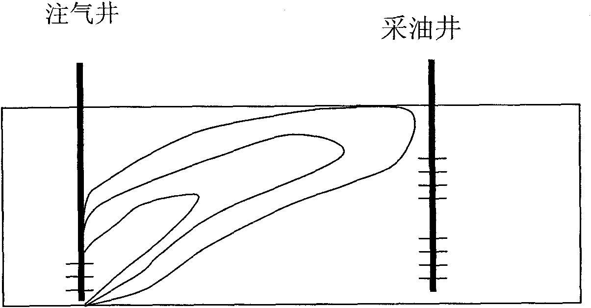
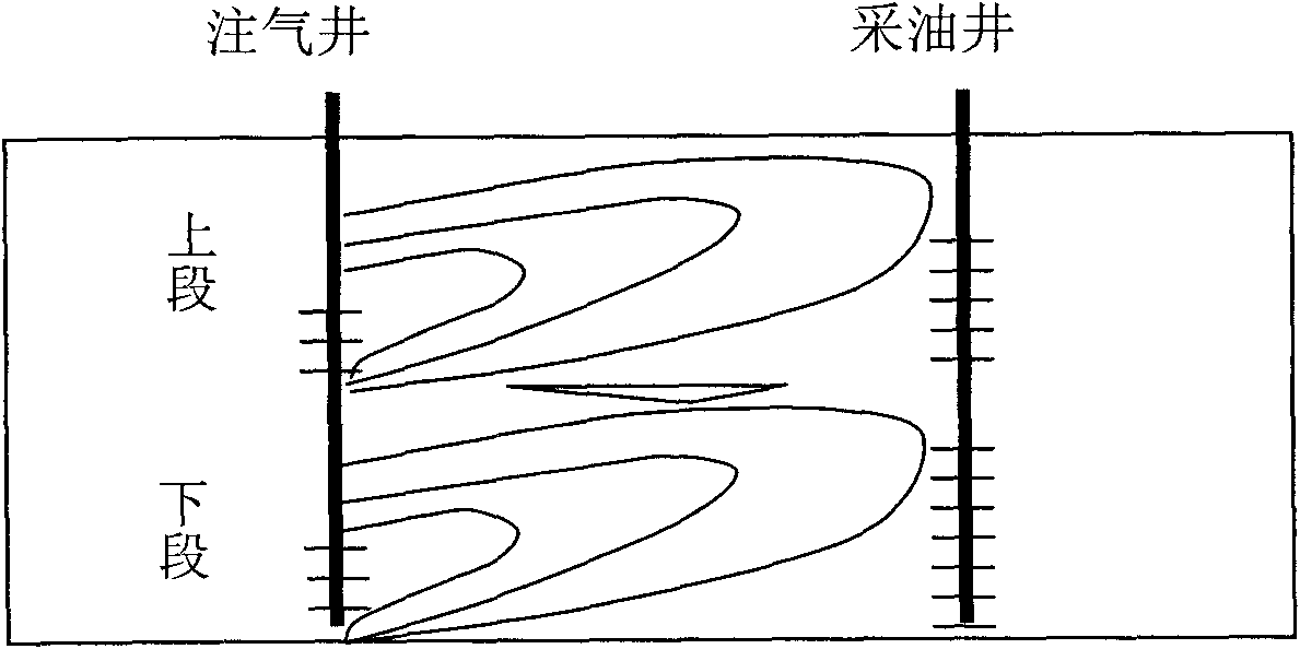
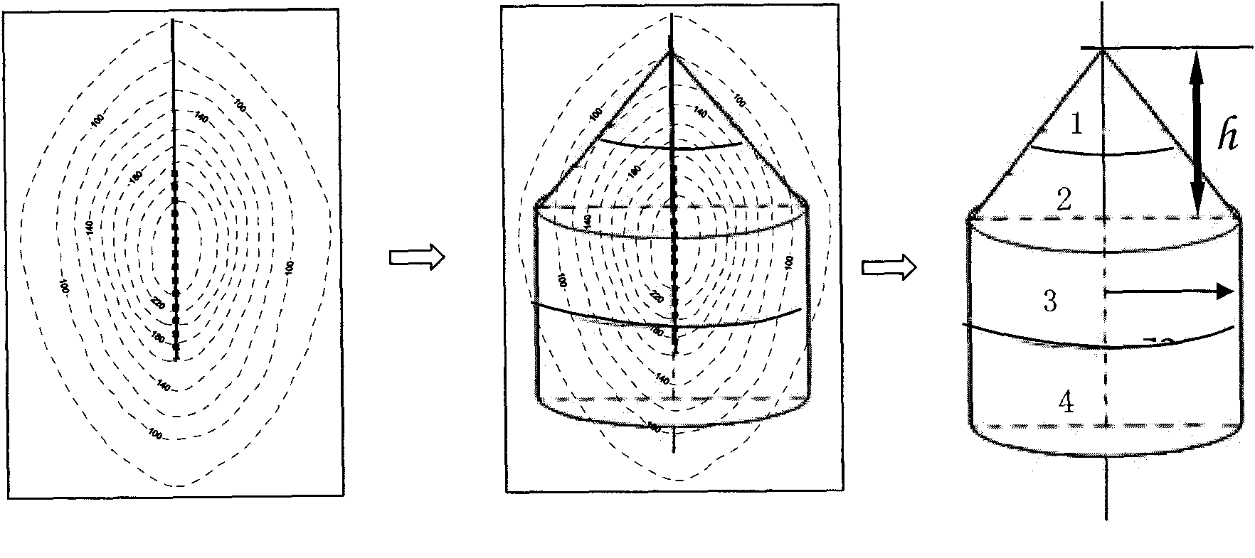
The invention relates to a method for improving recovery ratio of massive oil pool with large monolayer thickness by utilizing subsection fireflooding exploitation. The method comprises the following steps: selecting oil pool meeting the following requirements through exploration; taking viscosity-temperature inflection point temperature of which the oil layer temperature exceeds the temperature of underground raw oil as a boundary to judge whether the oil layer is explored or not, using the heating volume occupied by each small layer as a weight factor of output compartment, and carrying outoutput compartment according to a small layer output compartment module; distributing multistage grading perforations on a gas well casing by utilizing space thickness of the oil layer in the length wise direction and referring to the distribution of the interlayer in the oil layer, firing the perforations at the bottom inside each stage; and expanding the ultimate swept volume of the oil layer by making full use of the space of the oil layer in the length wise direction and the lapout characteristic of the combustion of oil in situ. The method of the invention improves the recovery ratio of a thickened oil block.

Description

technical field [0001] The invention relates to an enhanced recovery technology for heavy oil reservoirs, in particular to a method for increasing recovery by staged fire flooding for massive oil reservoirs with relatively large single-layer thickness. Background technique [0002] In-situ combustion, also known as underground combustion or intra-layer combustion, also known as fire-flooding, is a thermal oil recovery technology that generates heat inside the oil layer. Oil recovery by burning oil layer is to artificially create an environment in the reservoir that can oxidize and burn crude oil by using coke-like substances deposited on the mineral matrix during the pyrolysis reaction as fuel and oxygen injected into the air as a combustion aid under formation conditions. Under the condition of heat release, under the condition of continuous injection of hot air, the oil layer will burn to form a radial moving combustion zone, also known as the line of fire. The crude oil ...

Claims


Application Information

Patent Timeline
Patent Type & Authority Patents(China)
IPC IPC(8): E21B43/24E21B43/243
Inventor 张方礼赵洪岩曹光胜胡士清宫宇宁程仲平张新元王中元
Owner PETROCHINA CO LTD
Learn More