Decorative lamp
A technology for lamps and light-emitting devices, which is applied in the direction of lighting devices, lighting auxiliary devices, lighting device components, etc., can solve the problems of increased process and cost, falling off, easy damage of refraction sheets, etc., and achieves simple and easy production and stable structure , not easy to damage the effect
- Summary
- Abstract
- Description
- Claims
- Application Information
AI Technical Summary
Problems solved by technology
Method used
Image

Examples
specific Embodiment approach 1
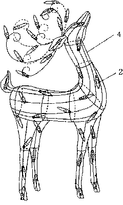
[0021] Such as figure 1 , 2 A decorative lamp shown includes a modeling frame 1 and a light emitting device 2 . The light emitting device 2 is located in the modeling frame 1 and adopts a colored light emitting diode (Light Emitting Diode, LED for short) or a light bulb. When using LEDs, energy saving, environmental protection, waterproof, shockproof, etc. can be realized. Cost savings when using bulbs. Modeling frame 1 is animal deer shape, certainly also can be other various animal shapes (as: rabbit, panda, horse etc.) or cartoon character shape (as: snowman, Santa Claus, Fuwa etc.) or box (as gift box, resurrection egg, star, etc.) shape.
[0022] The molding frame 1 includes a support frame 4 and a molding bar 3, all of which are made of opaque metal materials, and of course can also be made of plastic materials. Wherein the support frame 4 is an iron support, which plays the role of forming the whole animal modeling foundation and supporting the weight of the whole ...
specific Embodiment approach 2
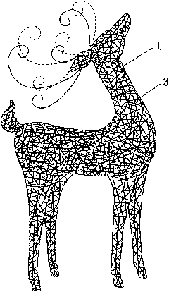
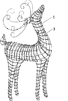
[0023] A decorative lamp includes a modeling frame and a light emitting device. Such as image 3 As shown, it differs from Embodiment 1 in that the molding strip 3 is made of plastic material, and is woven and wound on the support frame 4 to form a molding frame. The use of plastic materials can reduce costs and weight. The shape of the molding strip 3 is as Figure 4 As shown, it is a rectangular sheet with a twisted cross-section. The mesh shape formed by the weaving has the same size and regular mesh. After the light diffraction layer is reflected and diffracted, the deer body can be seen at different positions. To different regular distribution of light spots, so that the brilliance is varied.
specific Embodiment approach 3
[0024] Such as Figure 5 A decorative lamp shown includes a modeling frame 1 and a light emitting device 2 . It differs from Embodiment 1 in that the molding frame 1 is in the shape of a five-pointed star. Since the entire shape of the five-pointed star is simple and the structure is stable, there is no support frame on the molding structure, and the molding strips 3 made of metal are directly braided through the drawing process. To form a star shape, of course, the plastic molding strips in Embodiment 2 can also be twisted to form a star shape. During production, firstly form half of the five-pointed star shape, and after the light emitting device 2 is installed and fixed, the other half of the five-pointed star shape formed by braiding can be closed and connected with it.
PUM
 Abstract
Description
Claims
Application Information
 - R&D Engineer
- R&D Manager
- IP Professional
- Industry Leading Data Capabilities
- Powerful AI technology
- Patent DNA Extraction
Browse by: Latest US Patents, China's latest patents, Technical Efficacy Thesaurus, Application Domain, Technology Topic.
© 2024 PatSnap. All rights reserved.Legal|Privacy policy|Modern Slavery Act Transparency Statement|Sitemap