Air single regenerative burner

A single heat storage and air technology, applied to gas fuel burners, burners, combustion methods, etc., can solve problems such as insufficient fuel combustion, affecting burner life, and polluting the environment, achieving sufficient combustion, compact structure, and reduced The effect of emissions

Inactive Publication Date: 2010-08-11
HUATIAN ENG & TECH CORP MCC +1
View PDF0 Cites 5 Cited by
  • Summary
  • Abstract
  • Description
  • Claims
  • Application Information

AI Technical Summary

Problems solved by technology

This kind of burner has the following disadvantages: (1) In the heating stage of the burner, since the air gas belongs to diffusion combustion in the furnace, this will lead to insufficient combustion of the fuel, and the NO in the combustion product X (2) In the smoke exhaust stage of the burner, the residual gas in the gas pipeline may cause the pipeline to backfire, and in severe cases, a backfire explosion will occur, which poses a serious safety hazard; (3 ), some gas (such as natural gas) contains more CH 4 The gas is easy to crack at high temperature, and the gas is easy to crack and deposit carbon in the high temperature channel, which will block the channel, affect the life of the burner, and also cause a large waste of energy; however, the current burner design does not take corresponding measures to cool and burn. High temperature gas pipeline connected with mouth brick

Method used


Image

  • Air single regenerative burner
  • Air single regenerative burner
  • Air single regenerative burner

Examples


Embodiment 1

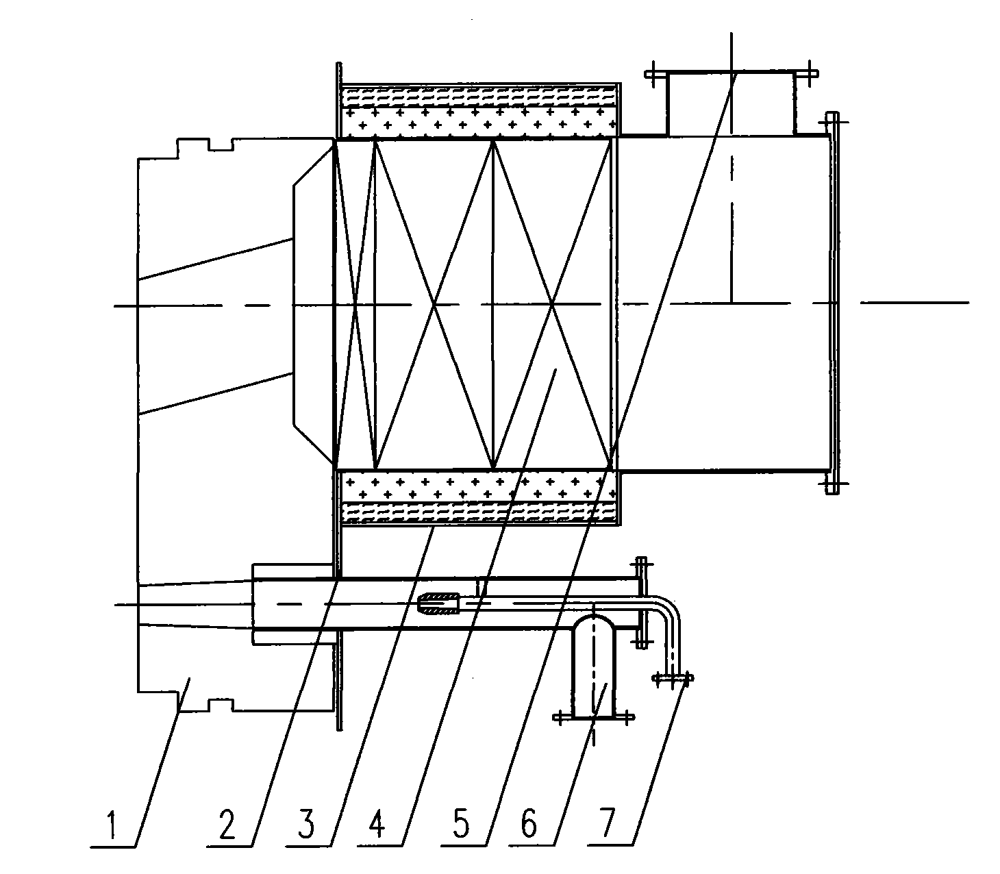
[0021] An air single heat storage burner, comprising a burner brick 1 and a burner mounting plate 2, a burner housing 3 is provided on the burner mounting plate 2, and a heat storage body 4 is provided in the burner housing 3, A secondary air pipeline 5 leading to the furnace is provided on the burner housing 3, and a gas pipeline 6 is provided outside the burner housing 3, and the end of the gas pipeline 6 is inserted into the burner brick 1, and in the gas pipeline 6 A primary air duct 7 is provided.

[0022] In this embodiment, the entire air-only regenerative burner is in a split structure, and the burner brick 1 is arranged in a labyrinth structure, so that it can effectively prevent the crossfire between the burner brick and the gap between the furnace wall, and further improve the cost efficiency. Invented safety features.

Embodiment 2

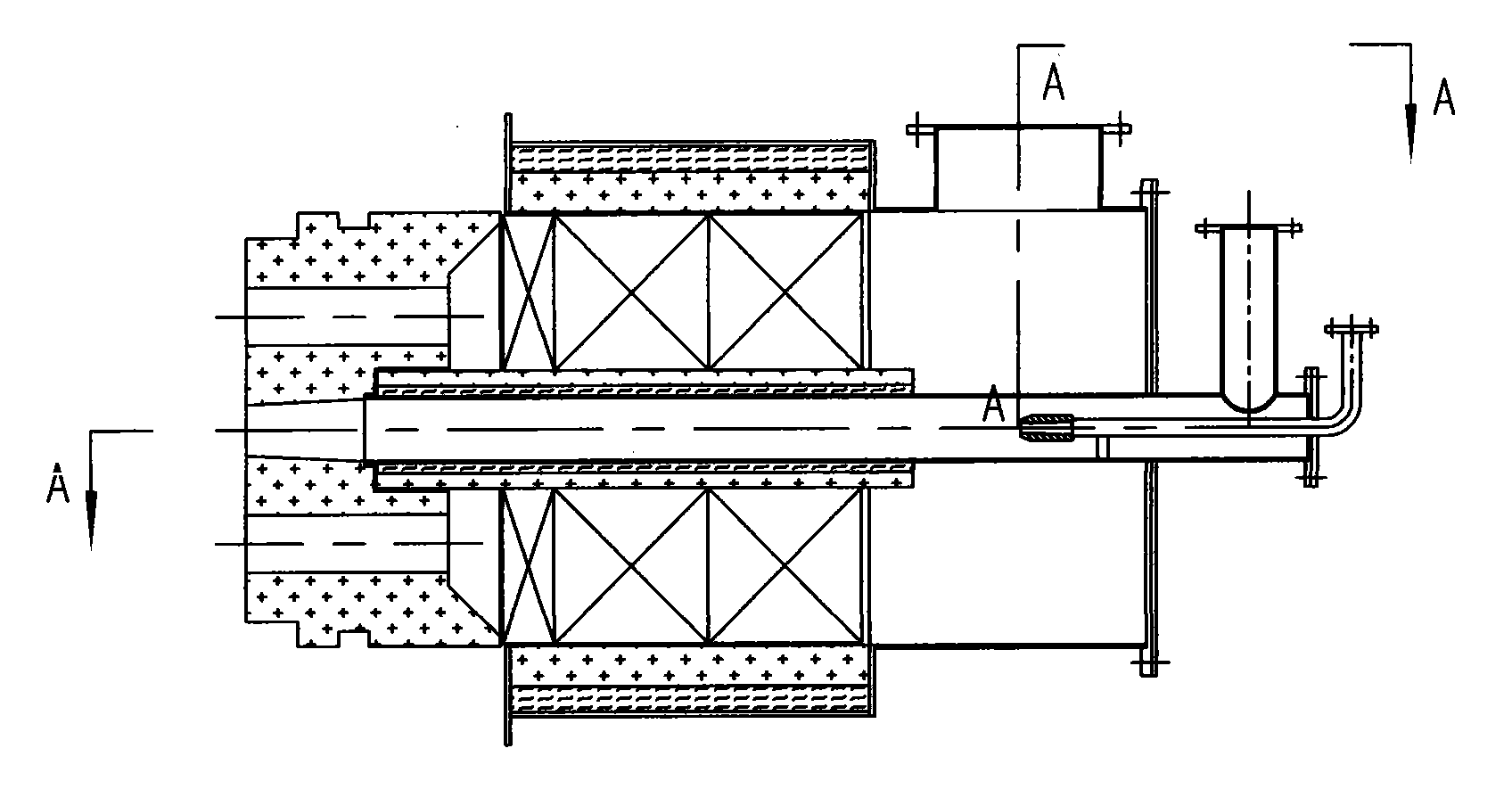
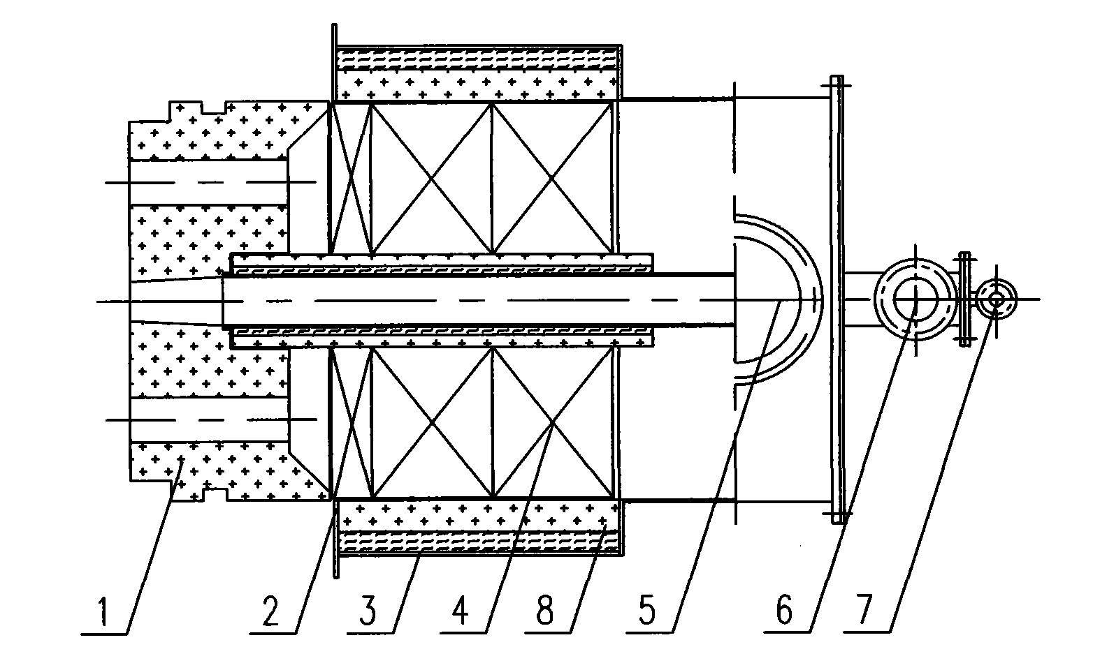
[0024] refer to figure 2 with image 3 , an air-only regenerative burner, including a burner brick 1 and a burner mounting plate 2, a burner housing 3 is provided on the burner mounting plate 2, and a heat storage body 4 is provided in the burner housing 3 , A secondary air pipeline 5 leading to the furnace body is provided on the burner housing 3, a gas pipeline 6 is provided in the burner housing 3, and the gas pipeline 6 passes through the regenerator 4 and the burner brick 1 part The exterior of the burner is provided with refractory insulation material 8, and the primary air pipe 7 is provided in the gas pipe 6, and the described burner brick 1 adopts a labyrinth structure.

[0025] In this embodiment, the entire burner has an integrated structure, which makes the structure of the burner more compact. The gas pipeline 6 and two air pipelines are placed in the burner housing 3, and the secondary air and the heat stored in the burner The body 4 is preheated to a high tem...


PUM


Abstract

The invention discloses an air single regenerative burner, which comprises a burner brick (1) and a burner mounting plate (2). A burner shell (3) is arranged on the burner mounting plate (2); a heat accumulator (4) is arranged in the burner shell (3); a secondary air pipeline (5) leading to a hearth is arranged on the burner shell (3); a gas pipeline (6) is arranged outside the burner shell (3); the tail end of the gas pipeline (6) is inserted into the burner brick (1); a primary air pipeline (7) is arranged in the gas pipeline (6); and the gas pipeline (6) and the primary air pipeline (7) can also be arranged in the burner shell (3). The air single regenerative burner of the invention can fully burn fuel in industrial furnaces and kilns so as to reduce the generation of NOX, save energy and protect environment, can effectively prevent backfire in the gas pipeline and has good safety.

Description

technical field [0001] The invention relates to an air single heat storage burner used in industrial furnaces. Background technique [0002] In the field of industrial furnaces, gas burners are often used to heat workpieces in industrial furnaces, and one of the gas burners is the regenerative burner. Usually, in the case of high calorific value of gas, the theoretical combustion temperature required in industrial furnaces can be reached only by air single heat storage and without preheating the gas. In this case, the burner used is air single heat storage burner. mouth. [0003] In the existing air single regenerative burner, the gas nozzle and the air single regenerative burner are separately arranged, and the primary air pipeline is not arranged in the gas pipeline. This kind of burner has the following disadvantages: (1) In the heating stage of the burner, since the air gas belongs to diffusion combustion in the furnace, this will lead to insufficient combustion of the...

Claims


Application Information

Patent Timeline
Patent Type & Authority Applications(China)
IPC IPC(8): F23D14/00F23D14/46F23D14/66
CPCY02E20/34
Inventor 朱理盛立新严云福
Owner HUATIAN ENG & TECH CORP MCC
Why Eureka
Try Eureka