
Auxiliary convection heat-accumulating type heater

A convective heating and heater technology, applied in the field of auxiliary convective heat storage heaters, can solve the problems of high heat storage material consumption, low heat release capacity, and easy formation of noise, etc., to achieve balanced heating temperature and effective heating effect Effect

Inactive Publication Date: 2013-10-02
红杉树电器有限公司
View PDF2 Cites 0 Cited by
  • Summary
  • Abstract
  • Description
  • Claims
  • Application Information

AI Technical Summary

Problems solved by technology

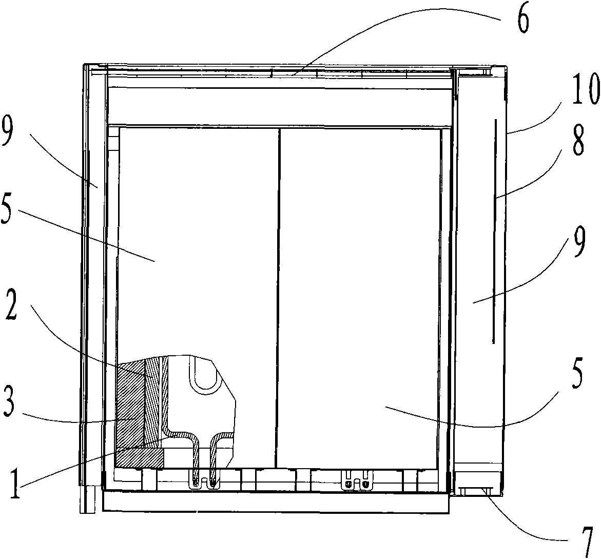
[0004] The purpose of the present invention is to solve the technical problems existing in the prior art, such as the low heat release capacity of the convection heat storage electric heater, the inability to provide stable heat supply, and the high consumption of heat storage materials, and to provide an auxiliary convection heat storage electric heater The heat release capacity is greatly improved, which can provide stable heat, save the amount of heat storage materials, and reduce the weight of the machine
[0005] Another purpose of the present invention is to solve the technical problems existing in the prior art that the forced convection heat storage type electric heater is easy to involve indoor dust or foreign matter inside the electric heater, easily generates noise, and has a complicated structure, etc., and provides a The auxiliary convection heat storage heater effectively avoids the problem of dust or foreign matter being involved in the electric heater and noise, and the structure is relatively simple, and its mass is smaller than that of the forced convection heat storage heater

Method used


Image

  • Auxiliary convection heat-accumulating type heater
  • Auxiliary convection heat-accumulating type heater
  • Auxiliary convection heat-accumulating type heater

Examples


Embodiment 1

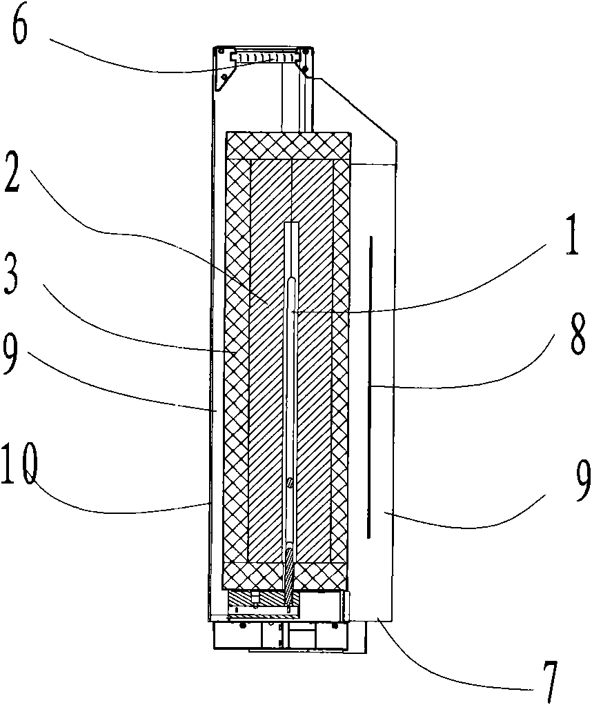
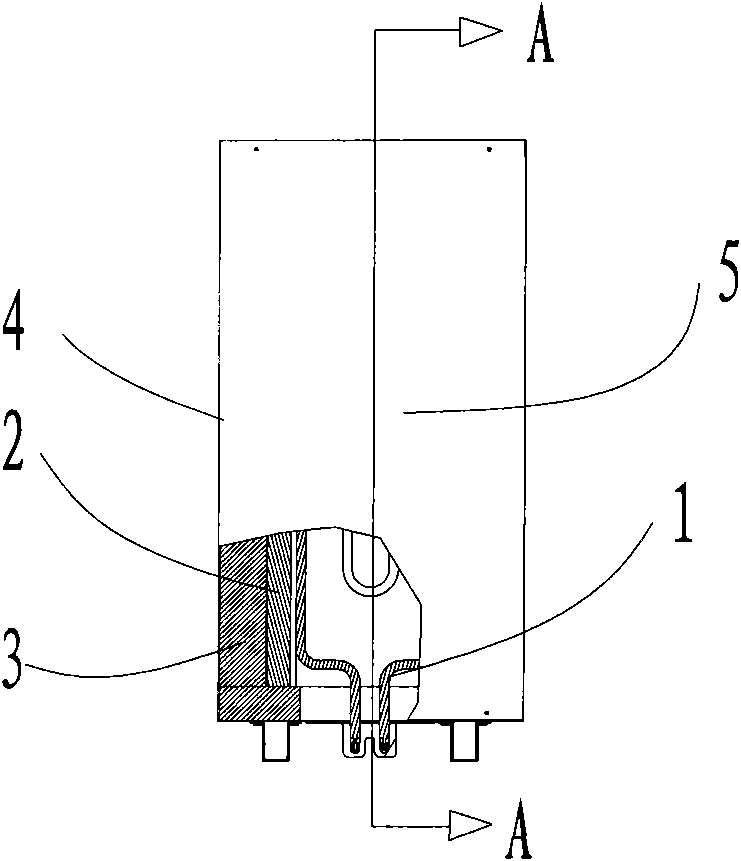
[0021] Embodiment 1: A kind of auxiliary convection regenerative heater of this embodiment such as figure 1 , 2 As shown, it includes a housing 10 and a heat storage device 5, the housing 10 is a semi-closed square body, the upper and lower parts of the housing 10 are formed with louvers respectively as the air inlet 7 and the air outlet 6, and the heat storage device 5 is installed in the housing 10 , the air gap between the inner surface of the housing 10 and the heat storage device 5 forms a smooth convection channel 9 with the air outlet 6 and the air inlet 7 of the housing 10, and the housing 10 is also provided with a heat transfer device to accelerate the convection flow by releasing heat energy. The auxiliary convection heating element 8 for the purpose of convection between the air in the channel 9 and the indoor air is connected to the temperature control device. The temperature of the air near the inner air intake 7 responds. The auxiliary convection heating elem...

Embodiment 2

[0025] Embodiment 2: The auxiliary convection heating element 8 of an auxiliary convection regenerative heater in this embodiment is an electric heater with several levels of power. The temperature control device controls the gear of the heating power of the electric heater by measuring the air temperature near the air inlet 7 in the heater shell 10 and comparing it with several set values ​​of the temperature control device, so as to adjust the heat released by the heat storage device 5 , to achieve a better energy-saving effect than that of Embodiment 1, and to ensure the balance of the room temperature. Other technical features are basically the same as in Embodiment 1.


PUM


Abstract

The invention relates to an auxiliary convection heat-accumulating type heater. The heater comprises a shell and at least one heat-accumulating device capable of storing and releasing heat energy, wherein the upper part of the shell is provided with a gas outlet, the lower part is provided with a gas inlet, the heat-accumulating device is arranged in the shell, and an air gap between the inner surface of the shell and the heat-accumulating device and the gas outlet and gas inlet of the shell constitute a convection channel. The invention is characterized in that the inside of the shell is also provided with an auxiliary convection heating element which releases heat energy to achieve the aim of accelerating the air convection in the convection channel and the convection of room air. The heater can be energized to generate heat energy in a low valley of an electricity grid and release the heat energy in a high valley of the electricity grid for heating room air; when the heat output of the heat-accumulating device is insufficient, the auxiliary convection heating element provides complementary convection heat energy by using little power, thus the indoor heating temperature can be more balanced; and the convection gas generated by auxiliary heating performs heat exchange, thus the residual heat energy in the heat-accumulating device can be brought out faster.

Description

technical field [0001] The present invention relates to a regenerative heater, in particular to an auxiliary convection regenerative heater for indoor use. Background technique [0002] At present, regenerative heaters have been more and more widely used. Chinese patent CN201302219Y discloses an automatic convection powder thermal storage electric heater, which includes a shell, an electric heating tube, and thermal storage powder. The housing is provided with upper and lower transverse partitions, and the thermal storage powder is filled in the upper and lower horizontal partitions. In the space between, the heating part of the electric heating tube is inserted into the heat storage powder, the top of the housing is provided with an upper louver, and the bottom is provided with a lower louver, and the upper transverse partition is the same as that of the housing. There is a space for forming an air collection chamber between the top, and a space for forming a pressure equa...

Claims


Application Information

Patent Timeline
Patent Type & Authority Patents(China)
IPC IPC(8): F24D15/02F24D19/10
CPCY02B30/12
Inventor 陈晓勇
Owner 红杉树电器有限公司
Learn More