Optical fiber point diffraction phase shift interferometry method of surface shape of large relative aperture sphere

A point-diffraction phase-shifting and relative aperture technology, applied in measurement devices, optical devices, instruments, etc., can solve the problems of many measurements, reduced measurement accuracy, low efficiency, etc., and achieves simple equipment structure, high precision, and guaranteed accuracy. Effect

Inactive Publication Date: 2010-08-11
BEIJING INSTITUTE OF TECHNOLOGYGY
View PDF3 Cites 14 Cited by
  • Summary
  • Abstract
  • Description
  • Claims
  • Application Information

AI Technical Summary

Problems solved by technology

[0007] The purpose of the present invention is to solve the problem that the sub-aperture splicing method that exists in the measurement process of the large relative aperture spherical surface with an angular aperture > 90° on the optical fiber point diffraction interferometer has many measurements, low efficiency, and reduced measu

Method used


Image

  • Optical fiber point diffraction phase shift interferometry method of surface shape of large relative aperture sphere
  • Optical fiber point diffraction phase shift interferometry method of surface shape of large relative aperture sphere
  • Optical fiber point diffraction phase shift interferometry method of surface shape of large relative aperture sphere

Examples


Embodiment Construction

[0024] The specific implementation manner of the present invention will be described in further detail below in conjunction with the accompanying drawings.

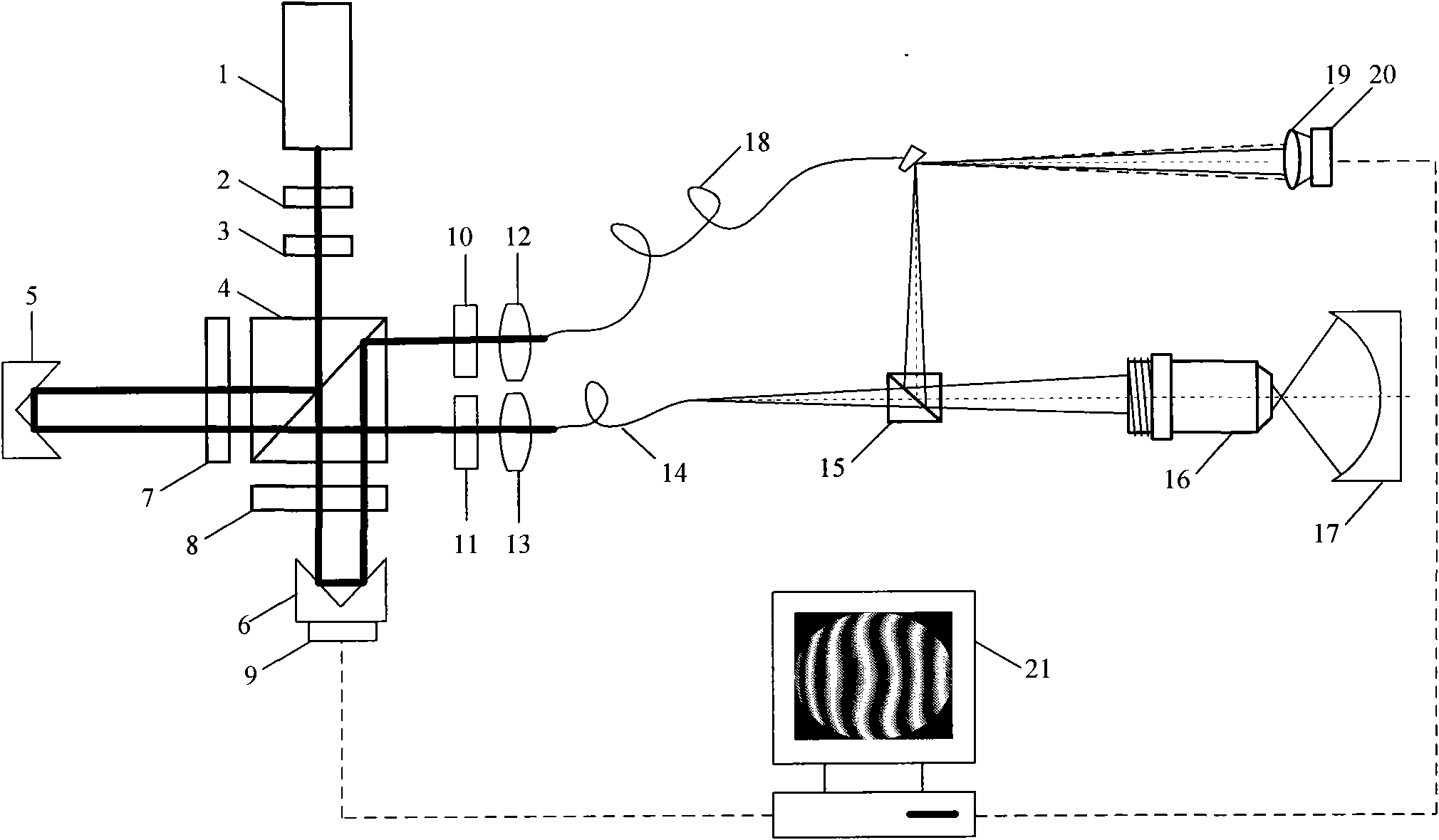
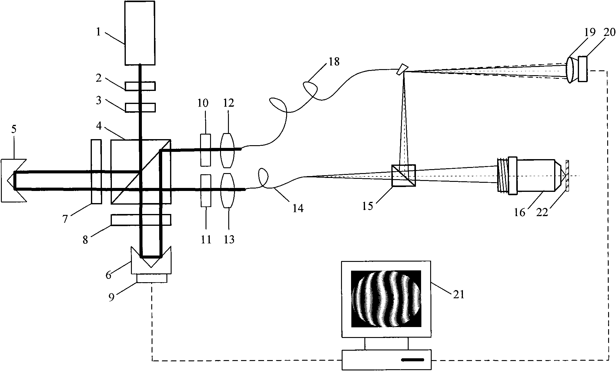
[0025] A large relative aperture spherical surface optical fiber point diffraction phase-shifting interferometry method. First select the following devices, such as figure 1 , figure 2 As shown, it includes: spectroscopic system, measuring optical fiber 14, beam splitting prism 15, microscope objective lens 16, measured large relative aperture spherical mirror 17, reference optical fiber 18, imaging lens 19, CCD camera 20, computer 21, plane mirror 22;

[0026] Among them, the beam splitting system includes a laser 1, an adjustable neutral density filter 2, a 1 / 2 wave plate 3, a polarizing beam splitting prism 4, a first right-angle prism 5, a second right-angle prism 6, and a first 1 / 4 wave plate 7. A second 1 / 4 wave plate 8 , a piezoelectric ceramic 9 , a first polarizer 10 , a second polarizer 11 , a first coupling ...


PUM


Abstract

The invention discloses an optical fiber point diffraction phase shift interferometry method of the surface shape of a large relative aperture sphere, belonging to the field of optical measurement. The method comprises the following steps of: firstly, measuring the diffraction wavefront of an optical fiber, transmitting the diffraction wavefront through a beam splitter prism, converting the diffraction wavefront into a measurement wavefront capable of covering a measured large relative aperture spherical mirror through a microobjective and reflecting on the surface of the measured spherical mirror; transmitting the microobjective by a reflecting wavefront carrying the surface shape information of the measured spherical mirror, reflecting the reflecting wavefront through the beam splitter prism, then converging to the end face of a reference optical fiber to form the measurement wavefront and converging the measurement wavefront with a reference wavefront diffracted by the reference optical fiber to form an interference; then removing the measured spherical mirror and keeping other optical elements unchanged; placing a plane mirror at the part of the focal point of the microobjective; and measuring astigmations brought by the microobjective, the beam splitter prism and the roughness of the end face of the reference optical fiber by using the same method. The invention is realized through two steps, and both the two steps utilize point diffraction spherical waves approximate to ideas as the reference wavefront and can realize the high-precision measurement of the surface shape of the large relative aperture sphere.

Description

technical field [0001] The invention belongs to the technical field of optical precision measurement, and relates to a high-precision interferometric measurement method of a large relative aperture spherical surface, which can realize full-scale high-precision interferometric measurement of a large relative aperture spherical surface without splicing sub-apertures. Background technique [0002] In recent years, large relative aperture spherical components such as ball bowls and spherical joints have been widely used in high-tech fields such as information technology, space technology, and remote sensing technology. The detection of such large relative aperture spherical elements has always been a difficult point in the field of optical measurement. The main reason is that the traditional optical interferometry method uses a high-precision standard lens to generate a reference wavefront, but it is very difficult to process a high-precision spherical standard lens, and it is e...

Claims


Application Information

Patent Timeline
IPC IPC(8): G01B11/24G01B9/02
Inventor 陈凌峰李杰周桃庚张旭升何川任雅青
Owner BEIJING INSTITUTE OF TECHNOLOGYGY
Why Eureka
Try Eureka