

Flexible composite laminate used for secondary cryogenic sealing barrier and adhered with lower laminate and its assembling method
A technology for sealing partitions, flexible layers, applied in adhesive heating bonding methods, lamination devices, household packaging, etc., to achieve the effect of avoiding surface contamination
Active Publication Date: 2010-08-18
HUTCHINSON SA
View PDF4 Cites 9 Cited by
- Summary
- Abstract
- Description
- Claims
- Application Information
AI Technical Summary
Problems solved by technology
Also, small leaks of liquid gas are very likely to propagate at the glass cloth yarns at the ply / adhesive interface where the applied glue forms the outer surface of the flexible ply and / or the underlying ply and may eventually do so through the secondary stage containment diaphragms, with potentially serious consequences as described above
Method used
View moreImage
Smart ImageViewing Examples

Examples
Embodiment Construction
Login to View More PUM
 Abstract
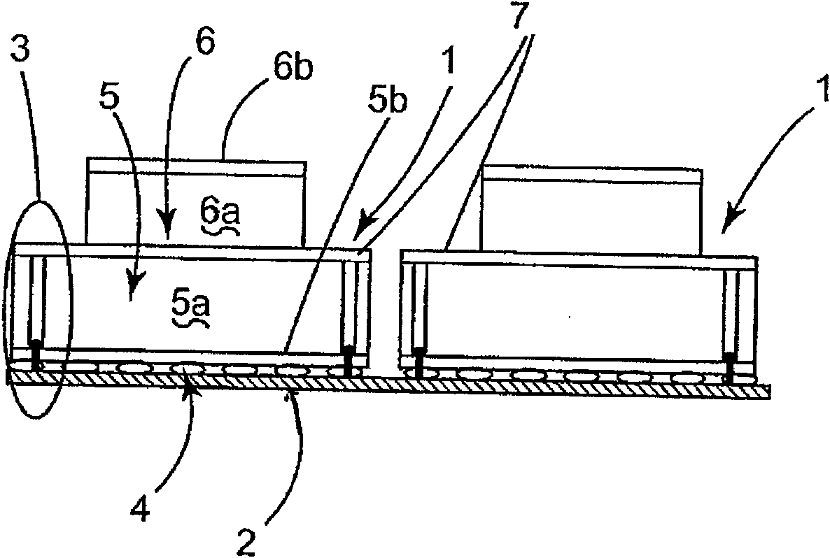
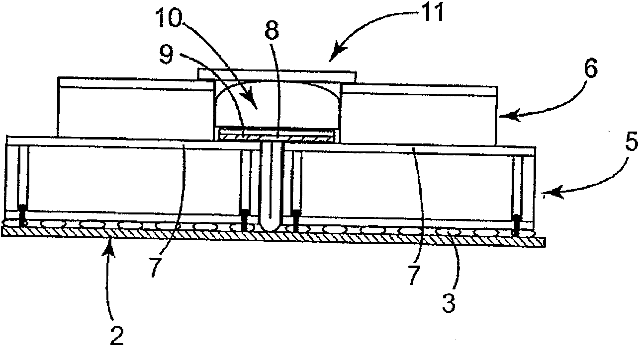
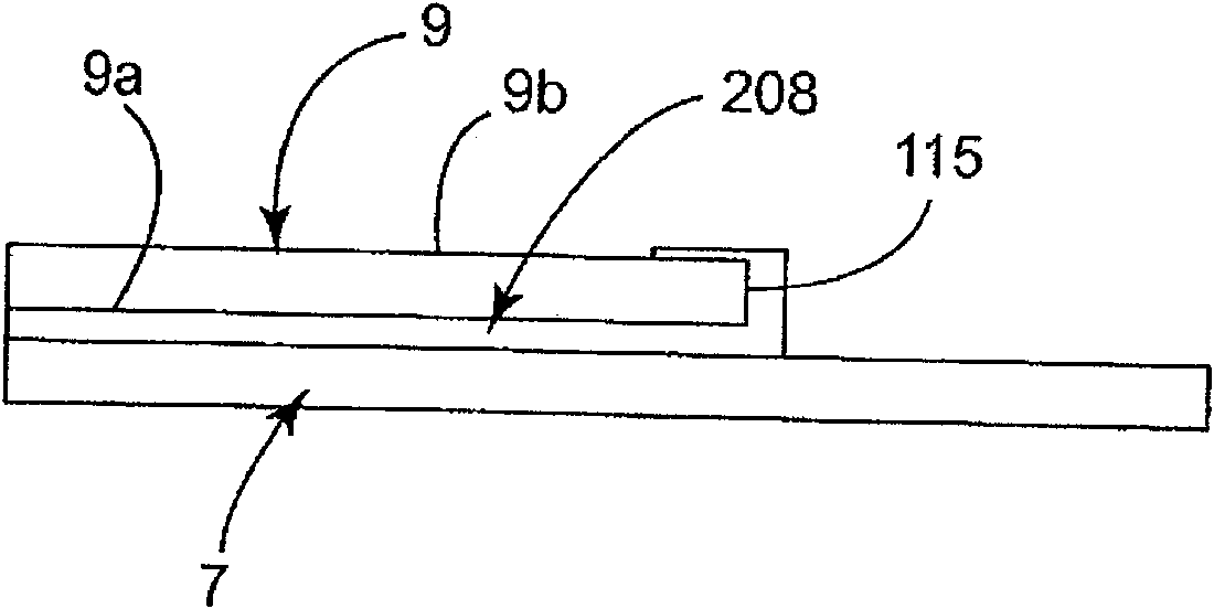
The invention relates to a flexible composite laminate (9) forming covering strip of a secondary cryogenic sealing barrier for container containing liquid methane, the secondary cryogenic sealing barrier comprises a flexible laminate belt adhered with a seam of a synthesis plate covered by another lower composite laminate. The invention also relates to a method for assembling the secondary barrier by adhering. The flexible composite laminate (9) is adhered to the seam of the adjacent synthesis plate covered by the lower laminate (7), the laminates comprise a metal foil dipped with an adhesion inserted between two fabrics. According to the invention, The flexible composite laminate is precoated with an adhesive by using a hot melt adhesive (208) cured by heat input, the hot melt adhesive is applied to tissues (9a) at a softening temperature to cover the external tissue of each lower laminate, and a peripheral edge (115) of the flexible laminate, the adhered assembly obtained by curing the adhesive contacted with the lower laminate by heating under the pressure condition, especially has improved mechanical strength and prevent the micro leakage of the low temperature liquid.
Description
Flexible laminate bonded to an underlying laminate and method of assembly thereof for a cryogenically sealed diaphragm technical field The present invention relates to flexible composite laminates forming a tape-like covering for a cryogenically sealed partition of a vessel containing, for example, liquid methane at -162°C, and to such a secondary partition, It consists of a strip of the flexible ply glued to the seam of a composite panel covered by another ply, the invention also relates to a method of assembling the secondary membrane by gluing. Background technique The design of the secondary containment partitions of the vessels in the methane transporter is based on the "Mark III" or "CS1" technology developed by the French company GTT, currently based on a laminate called a "Triplex" laminate, as leaked The partition of liquid methane is in direct contact with the cryogenic liquid if the primary partition parallel to the vessel wall is damaged or ruptured. This seco...
Claims
Login to View More Application Information
Patent Timeline
 IPC IPC(8): B32B7/12B32B15/14B32B37/12B32B37/10
CPCF17C2223/0161F17C2203/0329B32B15/08F17C2209/227C09J2463/006F17C2209/232F17C2203/0354F17C2260/036C09J2475/00B32B7/12C09J2463/00F17C2203/0636F17C2270/0107F17C2221/033F17C2203/0646F17C2203/0604C09J5/06B32B3/04B32B3/08B32B3/18B32B5/02B32B5/18B32B5/22B32B5/245B32B15/20B32B27/12B32B27/30B32B27/40B32B2250/44B32B2260/021B32B2260/046B32B2262/101B32B2307/30B32B2307/402B32B2307/50B32B2307/546B32B2439/00B32B2439/40
Inventor法比恩·莱洛伊迪迪埃·拉瓦所特
OwnerHUTCHINSON SA