Carbon fibre bobbin creel

A carbon fiber and creel technology, applied in the field of warp creel, can solve the problems of small resistance when the bobbin is rotated

Active Publication Date: 2010-08-18
JIANGSU XINYANG NEW MATERIALS CO LTD
View PDF5 Cites 17 Cited by
  • Summary
  • Abstract
  • Description
  • Claims
  • Application Information

AI Technical Summary

Problems solved by technology

[0006] In order to solve the problem of low resistance when the bobbin is rotating in the prior art, the present invention provides a carbon fi

Method used


Image

  • Carbon fibre bobbin creel
  • Carbon fibre bobbin creel
  • Carbon fibre bobbin creel

Examples


Embodiment Construction

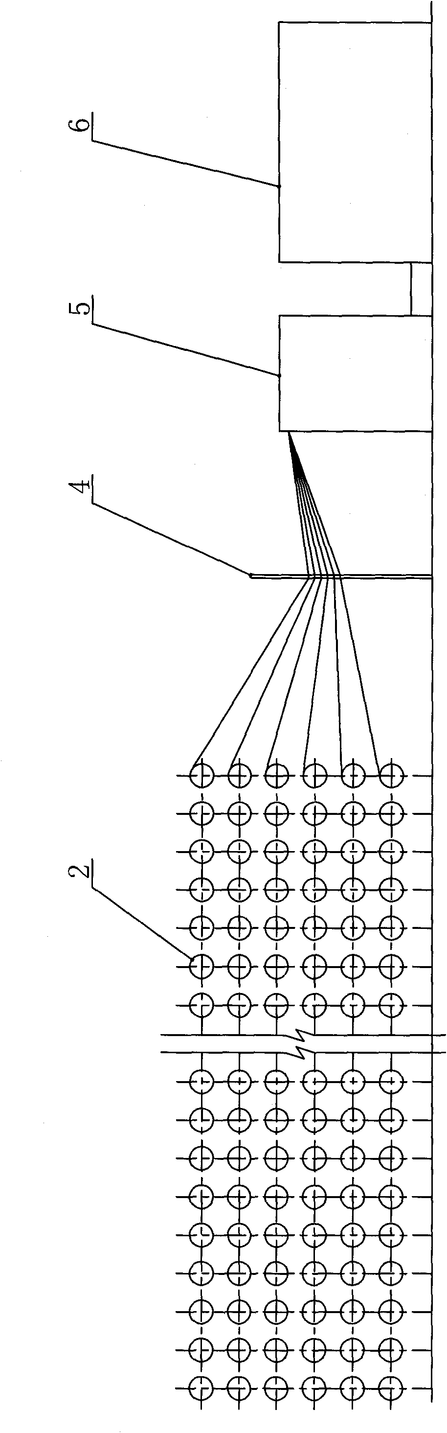
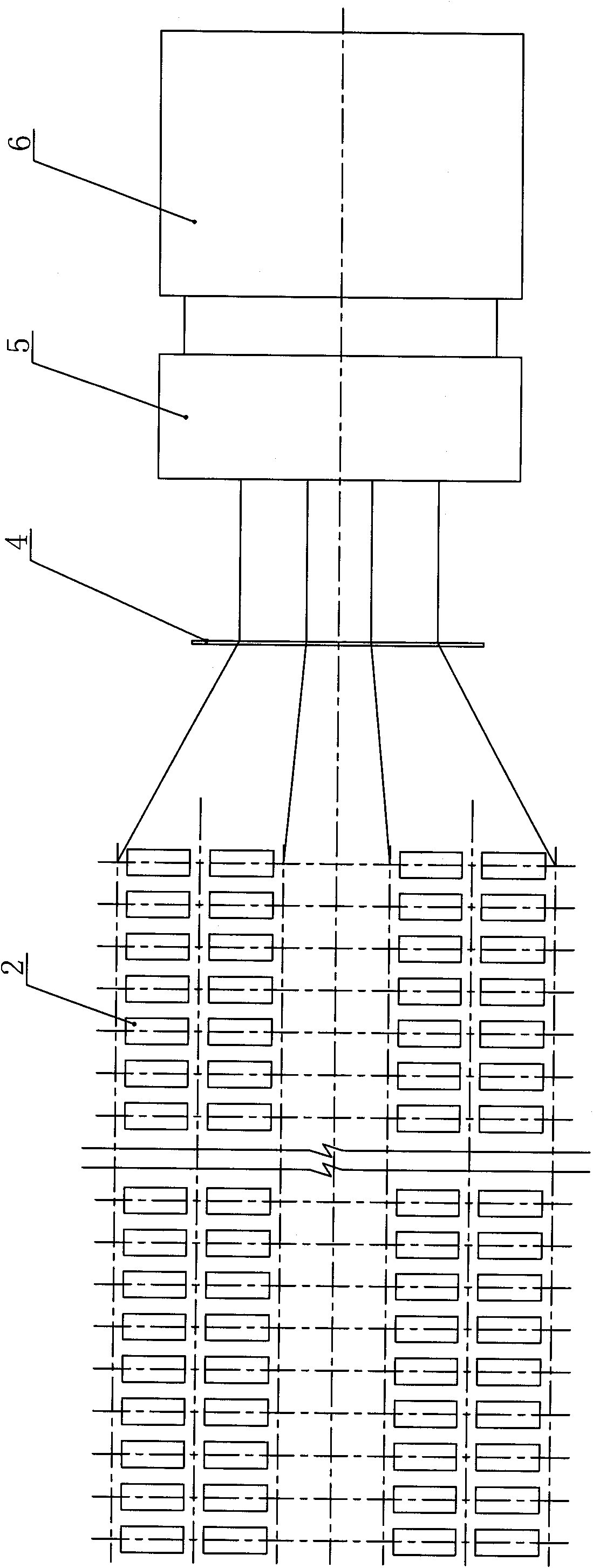
[0020] Such as figure 2 and image 3 As shown, the creel of the present invention is installed behind the rapier loom 6 and is arranged in two or three rows. The carbon fiber tubes 2 in each row are symmetrically distributed, and there are six layers in total. The carbon fiber bundles released from the carbon fiber tubes 2 pass through successively. The yarn collection frame 4 and the external tension system 5 enter the rapier loom 6 .

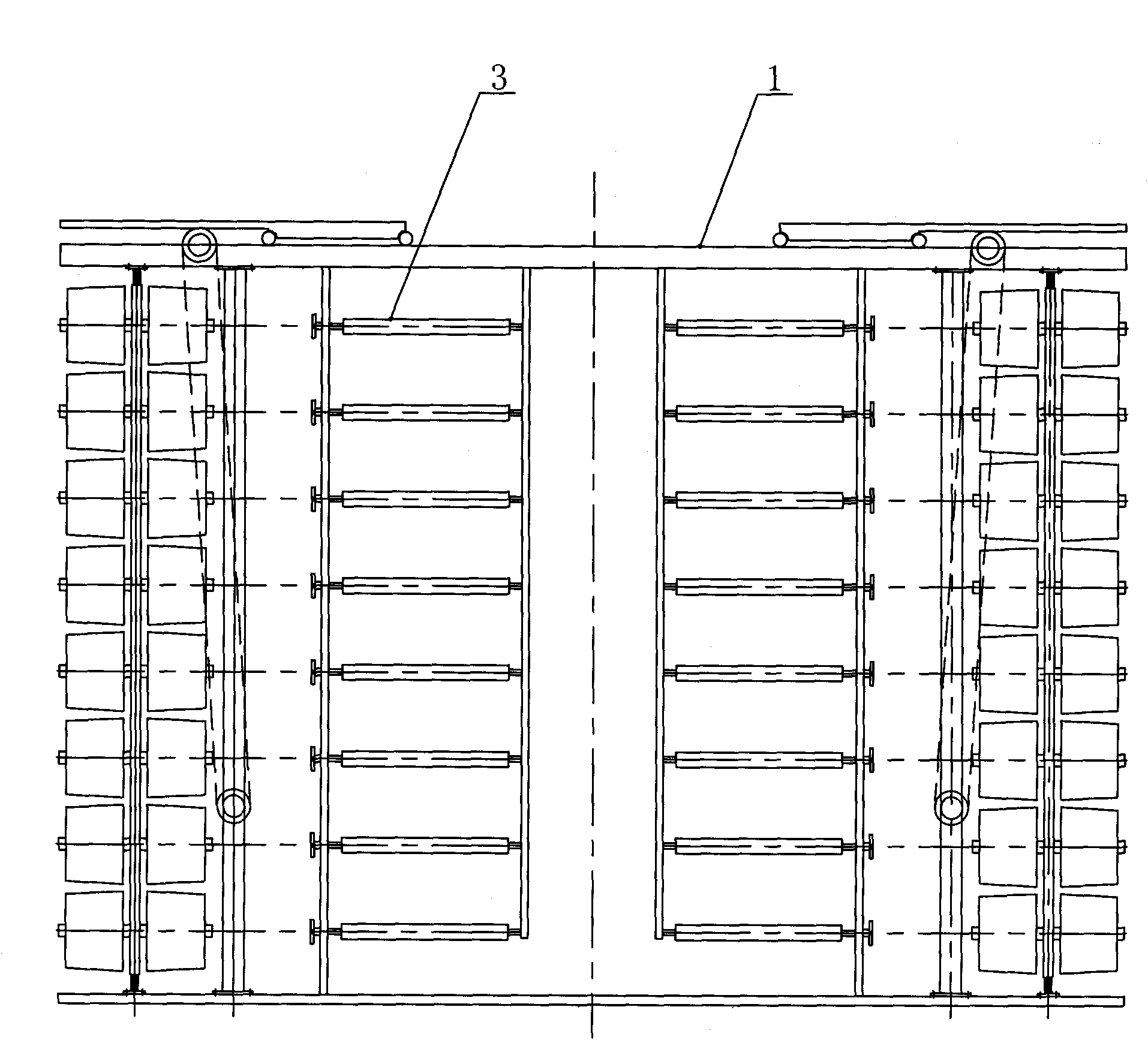
[0021] Such as Figure 4 and Figure 5 As shown, a wire guide plate 7 is provided every five carbon fiber tubes in the horizontal direction of the creel. The wire guide plate 7 is parallel to the axis of the spindle rod, and the middle part is provided with an alumina guide groove 7a, that is, the periphery of the guide groove is covered with An aluminum oxide layer keeps the guide channels smooth and burr-free, avoiding abrasion to the carbon fibers. The length of the alumina guide groove 7a is shorter than that of the carbon fiber cylin...


PUM


Abstract

The invention discloses a carbon fibre bobbin creel in the field of textile machinery, which comprises a frame, a spindle blade and a carbon fibre bobbin, wherein the spindle blade is arranged on the frame; the carbon fibre bobbin is sleeved on the spindle blade; each spindle blade and each carbon fibre bobbin are distributed on the frame in an array; fixed and movable friction plates engaged with each other are arranged outside an inner end plate of the carbon fibre bobbin; a first rubber layer is arranged between the fixed friction plate and the frame; a second rubber layer is arranged between the movable friction plate and the inner end plate of the carbon fibre bobbin and adhered to the inner end plate of the carbon fibre bobbin; the first rubber layer is adhered to the frame; the end of the spindle blade is provided with a tension spring and a nut; and a silk guide plate is arranged every five carbon fibre bobbins and provided with an aluminium oxide guide groove. The bobbin on each spindle blade of the bobbin creel can automatically provide tension force for the carbon fibre and adjust the tension force according to the thickness of the carbon fibre bundle; and the carbon fibre led out has basically the same tension force and less wearing.

Description

technical field [0001] The invention relates to a warp creel in the field of textile machinery, in particular to a carbon fiber creel. Background technique [0002] Large tow carbon fiber woven fabric is a kind of carbon fiber reinforced skeleton material for composite materials. It is usually woven by rigid rapier looms and is widely used in the repair and reinforcement of components of aviation and spacecraft, bridges, buildings and large structures. Because the carbon fiber bundles used as warp yarns are very thick, when weaving according to the traditional process, it is easy to cause the carbon fibers to be worn and broken, which will have a very adverse effect on the mechanical properties of the fabric. The loom warp delivery system in the form of weaving beams cannot meet the weaving needs of continuous and mass production. Therefore, the large tow carbon fiber warp yarns are directly drawn out from the creel and entered into the loom for weaving, which has become th...

Claims


Application Information

Patent Timeline
IPC IPC(8): D02H1/00
Inventor 李俊
Owner JIANGSU XINYANG NEW MATERIALS CO LTD
Why Eureka
Try Eureka