Wave-front sensor and corrector aligning device in self-adaptive optical system

A technology of wavefront corrector and wavefront sensor, applied in optics, measuring devices, scientific instruments, etc., can solve the problems of low precision and low intelligence

Active Publication Date: 2010-08-18
INST OF OPTICS & ELECTRONICS - CHINESE ACAD OF SCI
View PDF3 Cites 21 Cited by
  • Summary
  • Abstract
  • Description
  • Claims
  • Application Information

AI Technical Summary

Problems solved by technology

[0003] The problem solved by the device of the present invention is: to overcome the deficiencies of the existing manual alignment adaptive optics system, such as low precision and low intelligence, in the wavefront sensor and wavefront corrector, and provide an adaptive optics system that can accurately measure An alignment device that adjusts the position mismatch error between the wavefront sensor and the wavefront corrector and realizes the precise alignment of the two. The measurement of the position error includes the horizontal and vertical translational mismatch errors and The rotation mismatch error of the wavefront sensor around the center of the wavefront corrector, the position of the wavefront sensor is moved and rotated by the translation stage controller and the electronically controlled translation stage, and the wavefront sensor and the wavefront corrector are accurately aligned to realize the alignment between the wavefront sensor and the wavefront corrector. Intelligent and precise alignment of the wavefront corrector improves the correction capability of the adaptive optics system

Method used


Image

  • Wave-front sensor and corrector aligning device in self-adaptive optical system
  • Wave-front sensor and corrector aligning device in self-adaptive optical system
  • Wave-front sensor and corrector aligning device in self-adaptive optical system

Examples


Embodiment Construction

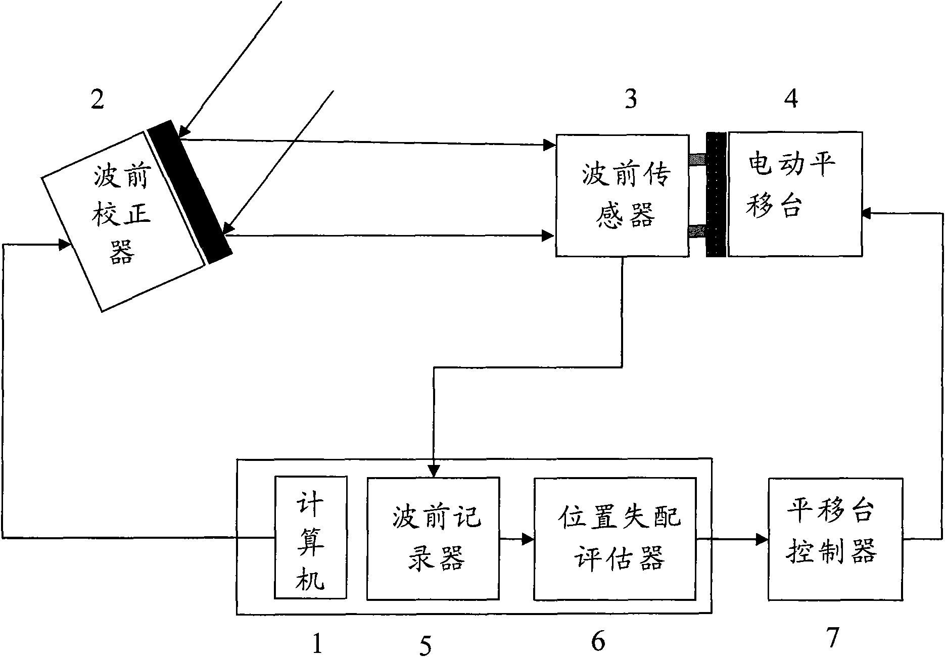
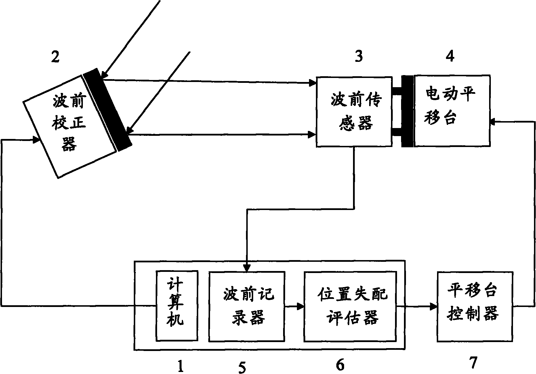
[0035] like figure 1 As shown, the embodiment of the present invention includes computer 1, wavefront corrector 2 (using independent unit continuous surface deformable mirror, or independent unit discrete surface deformable mirror, or liquid crystal corrector), wavefront sensor 3 (using Hartmann wavefront sensor or interferometer), electronically controlled translation stage 4, wavefront recorder 5, position mismatch estimator 6, and translation stage controller 7; the computer marks the wave by applying voltage to multiple independent drive units in the wavefront corrector The position of the front corrector, the wavefront sensor detects the wavefront shape distribution or the wavefront slope distribution caused by the marking of each independent drive unit in the wavefront corrector, and the wavefront recorder records it and sends it to the position mismatch evaluator, the position The mismatch evaluator calculates the center position of each marked independent drive unit in...


PUM


Abstract

The invention provides a wave-front sensor and corrector aligning device in a self-adaptive optical system, which consists of a wave-front sensor, a wave-front recorder, a wave-front corrector, an electric control transverse moving table, a position mismatching evaluating device, a transverse moving table controller and a computer, wherein the electric control transverse moving table can transversely move and rotate, the position of the wave-front corrector is marked in a mode of exerting the voltage to an independent unit of the wave-front corrector through the computer, and the position mismatching between the wave-front sensor and the wave-front corrector is measured through the self wave-front detection capability of the wave-front sensor. Light beams enter the wave-front sensor through being reflected by the wave-front corrector, the face shape information of the wave-front corrector detected by the wave-front sensor is recorded by the wave-front recorder, the position mismatching evaluating device carries out the calculation according to the recorded information of the wave-front recorder and outputs the position mismatching data into the transverse moving table controller, and finally, the transverse moving table controller is used for controlling the electric control transverse moving table for completing the position regulation of the wave-front sensor. The invention can accurately align the positions of the wave-front sensor and the wave-front corrector, can greatly improve the aligning precision and the aligning efficiency of the wave-front sensor and the wave-front corrector, and can ensure the wave-front control capability of the self-adaptive system.

Description

technical field [0001] The invention relates to a position mismatch measurement and alignment system of a wavefront sensor and a wavefront corrector in an adaptive optics system. Background technique [0002] In the adaptive optics system, the positions of the wavefront corrector and the wavefront sensor need to meet the optical correspondence, and the wavefront sensor and the wavefront corrector are two independent devices, and the relative translation and rotation of the two will vary to varying degrees. Changing this relationship affects the wavefront correction capability of the adaptive optics system. In the actual working process of the adaptive optics system, once the two positions are mismatched, we will adjust it manually. However, this alignment method lacks accurate alignment basis, and the alignment accuracy cannot be guaranteed . At the same time, the traditional alignment method also limits the application field and the expansion of the application scale of a...

Claims


Application Information

Patent Timeline
Patent Type & Authority Applications(China)
IPC IPC(8): G02B26/06G01J9/02
Inventor 顾乃庭杨泽平黄林海饶长辉
Owner INST OF OPTICS & ELECTRONICS - CHINESE ACAD OF SCI
Why Eureka
Try Eureka