Transformer structure
A transformer and housing technology, applied in the field of transformer structure, can solve the problems of transformer exposed electromagnetic, interference, poor heat dissipation of transformer, etc., and achieve the effect of reducing electromagnetic interference and reducing impact
- Summary
- Abstract
- Description
- Claims
- Application Information
AI Technical Summary
Problems solved by technology
Method used
Image

Examples
Embodiment Construction
[0035] Some typical embodiments embodying the features and advantages of the present invention will be described in detail in the following description. It should be understood that the present invention is capable of various changes in different forms without departing from the scope of the present invention, and that the description and drawings thereof are illustrative in nature and not limiting of the present invention.
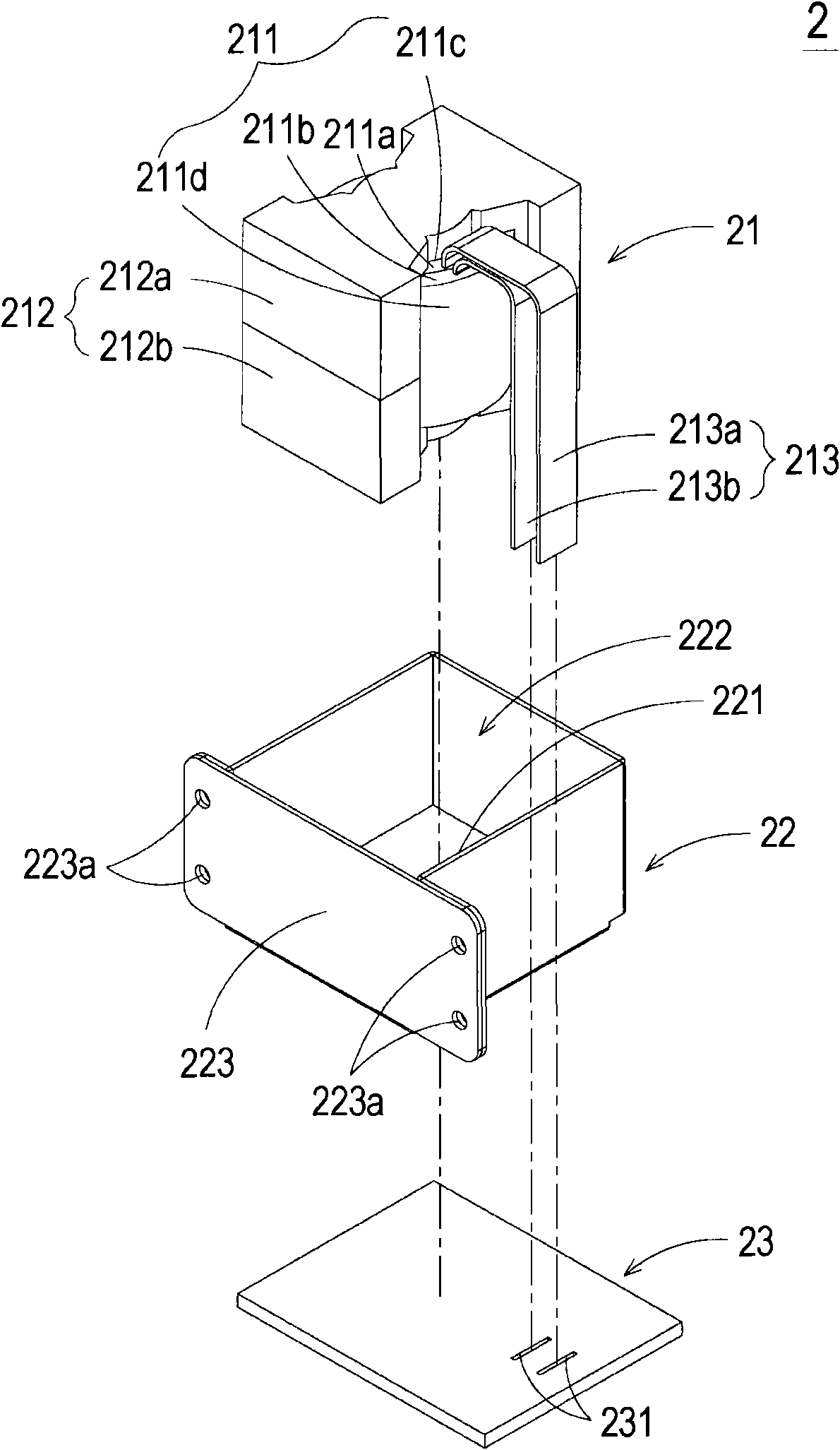
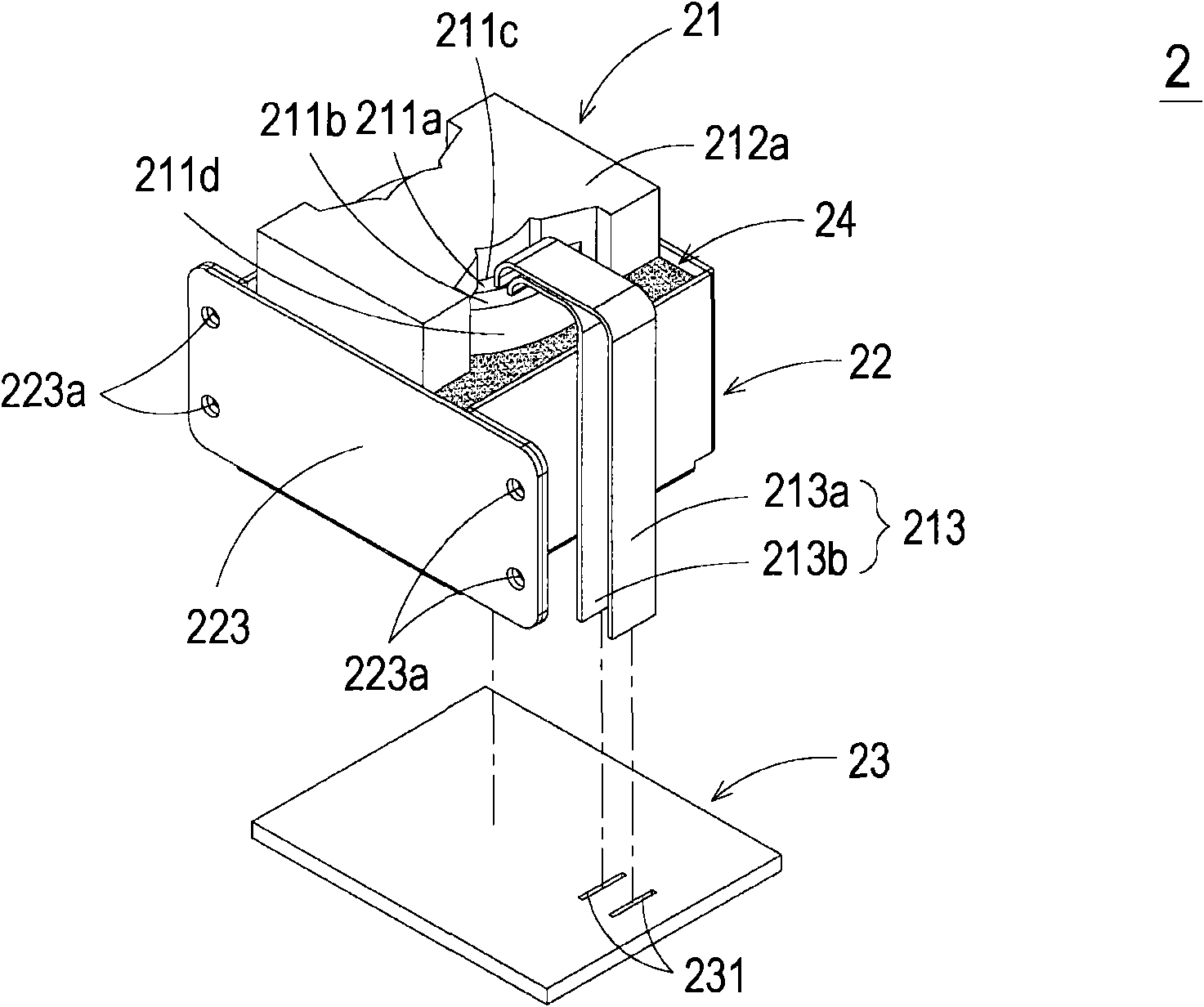
[0036] see Figure 2A to Figure 2C , which is a structural schematic diagram of the transformer structure of the first preferred embodiment of the present invention. As shown in the figure, the transformer 2 of the present invention is mainly composed of an inductor unit 21, a housing 22 and a heat conducting layer.
[0037] Such as Figure 2A As shown, the inductance unit 21 includes a winding part 211 and a magnetic core group 212. In some embodiments, the winding part 211 has a primary winding 211a and a secondary winding 211b. Taking this embodiment ...
PUM
 Abstract
Description
Claims
Application Information
 - Generate Ideas
- Intellectual Property
- Life Sciences
- Materials
- Tech Scout
- Unparalleled Data Quality
- Higher Quality Content
- 60% Fewer Hallucinations
Browse by: Latest US Patents, China's latest patents, Technical Efficacy Thesaurus, Application Domain, Technology Topic, Popular Technical Reports.
© 2025 PatSnap. All rights reserved.Legal|Privacy policy|Modern Slavery Act Transparency Statement|Sitemap|About US| Contact US: help@patsnap.com