Baseplate support device

A supporting device and substrate technology, applied in optics, instruments, electrical components, etc., can solve the problems of residual glue left on the back of the glass substrate, inability to fix, warping of heat-resistant tape, etc., to avoid offset or poor alignment, Reduce the contact area and avoid burns

Inactive Publication Date: 2010-08-18
AU OPTRONICS CORP
View PDF4 Cites 21 Cited by
  • Summary
  • Abstract
  • Description
  • Claims
  • Application Information

AI Technical Summary

Problems solved by technology

In the above-mentioned prior art, the bar-shaped member 12 is prone to warping and deformation due to heat, while the column-shaped member 22 is easy to fall off. Therefore, no matter whether it is the bar-shaped member 12 or the column-shaped member 22, it is impossible to securely fix it on the base. position, and once the position shifts, it will cause panel defects (Mura defect)
In addition, heat-resistant adhesive tapes 14 and 24 may also warp due to heat, or even fall off, leaving residual glue on the back of the glass substrate.
Furthermore, since the strip member 12 or the columnar member 22 is pasted on the base 10, 20 by means of the heat-resistant adhesive tape 14, 24, not only the position is not easy to adjust, but also the user sticks the heat-resistant adhesive tape 14, 24 at high temperature. there is a risk of getting burned

Method used


Image

  • Baseplate support device
  • Baseplate support device
  • Baseplate support device

Examples


Embodiment Construction

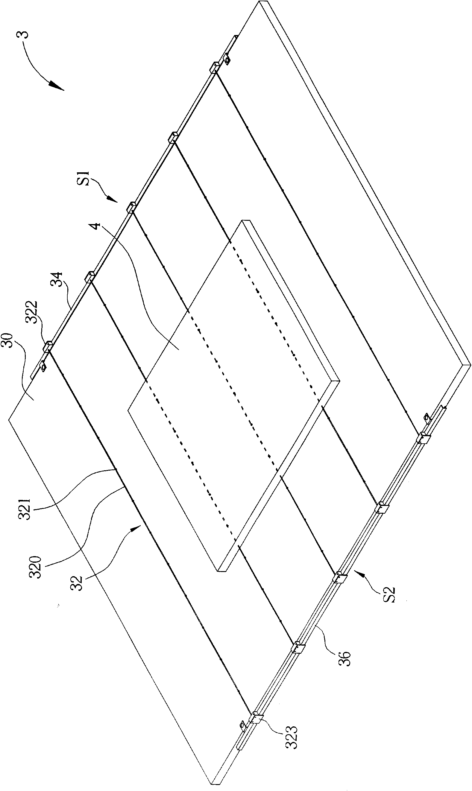
[0039] see image 3 as well as Figure 4 , image 3 is a schematic diagram of a substrate supporting device 3 according to an embodiment of the present invention, Figure 4 for image 3 An exploded view of the support structure 32 in . Such as image 3 As shown, the substrate supporting device 3 includes a base 30 , a supporting structure 32 , a first track 34 and a second track 36 . The substrate supporting device 3 is used for supporting the substrate 4 . In practical applications, the substrate 4 can be a glass substrate of a liquid crystal display, and the substrate supporting device 3 can be used in various heat treatment processes in the liquid crystal display process (such as pre-baking after coating an alignment film), so as to support the substrate 4 on a baking tray ( That is, on the base 30). The first track 34 is arranged on the first side S1 of the base 30, and the second track 36 is arranged on the second side S2 of the base 30, wherein the first side S1 i...


PUM


Abstract

The invention discloses a baseplate support device used for supporting a baseplate, which comprises a pedestal and a support structure, wherein the support structure is arranged on the pedestal, the support structure comprises a linear member and a plurality of spherical members, the spherical members are connected in series on the linear member, and the spherical members support the baseplate on the pedestal in the point-contact mode. By using the spherical members to support the baseplate on the pedestal in the point-contact mode, the invention can reduce the area in contact with the baseplate, and lower the possibility that the support structure is stuck to the baseplate at high temperature, thereby avoiding the deviation or the bad alignment of the baseplate.

Description

technical field [0001] The invention relates to a substrate supporting device, in particular to a substrate supporting device which can be used in various stages of liquid crystal display baking processes. Background technique [0002] Generally speaking, the heat treatment process in the liquid crystal display process has a series of sequences, including drying after cleaning, photoresist pre-bake, pre-baking and firing after coating the alignment film, and frame glue firing after panel bonding. Cheng and so on. In each heat treatment process, it is necessary to use a substrate supporting device to support the glass substrate. [0003] see figure 1 as well as figure 2 , figure 1 is a schematic diagram of a substrate supporting device 1 in the prior art, figure 2 It is a schematic diagram of another prior art substrate supporting device 2 . Such as figure 1 As shown, the base 10 of the substrate supporting device 1 is provided with a plurality of strip-shaped member...

Claims


Application Information

Patent Timeline
Patent Type & Authority Applications(China)
IPC IPC(8): H01L21/683G02F1/1333
Inventor 江子良
Owner AU OPTRONICS CORP
Why Eureka
Try Eureka