Large-bandwidth continuous time common-mode feedback circuit and design method thereof

A common-mode feedback and design method technology, applied in the direction of negative feedback circuit layout, differential amplifier, DC-coupled DC amplifier, etc., can solve the problem that the phase margin of the common-mode feedback circuit is difficult to meet, and the common-mode feedback loop is difficult to meet the application Requirements and other issues to achieve good stability

Inactive Publication Date: 2010-08-18
TIANJIN UNIV
View PDF2 Cites 18 Cited by
  • Summary
  • Abstract
  • Description
  • Claims
  • Application Information

AI Technical Summary

Problems solved by technology

Usually, the error amplifier is a one-stage common-source amplification structure, so that the common-mode feedback loop adds at least one more common-source amplification. For the application requirements of large bandwidth, it is difficult for the common-mode feedback loop to meet the application requirements of sufficient phase margin.
[0010] like image 3 As shown, in the traditional continuous-time common-mode feedback, the feedback point of the common-mode feedback is connected to the gate of the bias tube in the op amp...

Method used


Image

  • Large-bandwidth continuous time common-mode feedback circuit and design method thereof
  • Large-bandwidth continuous time common-mode feedback circuit and design method thereof
  • Large-bandwidth continuous time common-mode feedback circuit and design method thereof

Examples


Embodiment Construction

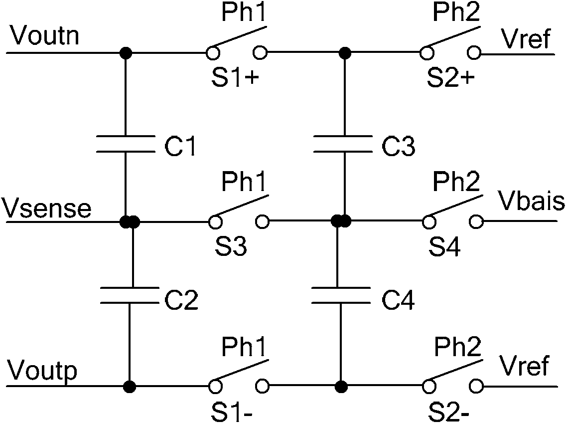
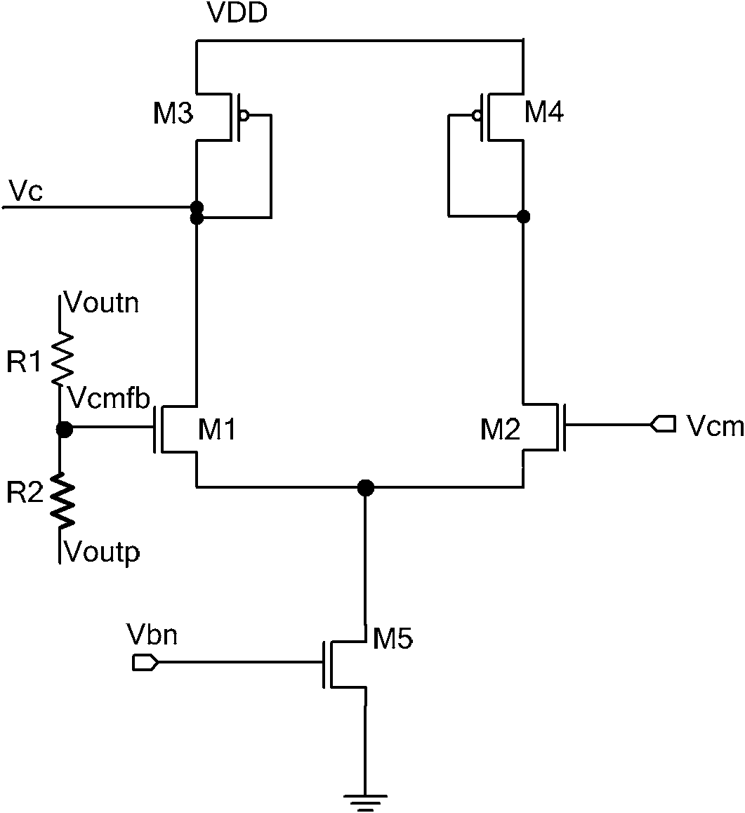
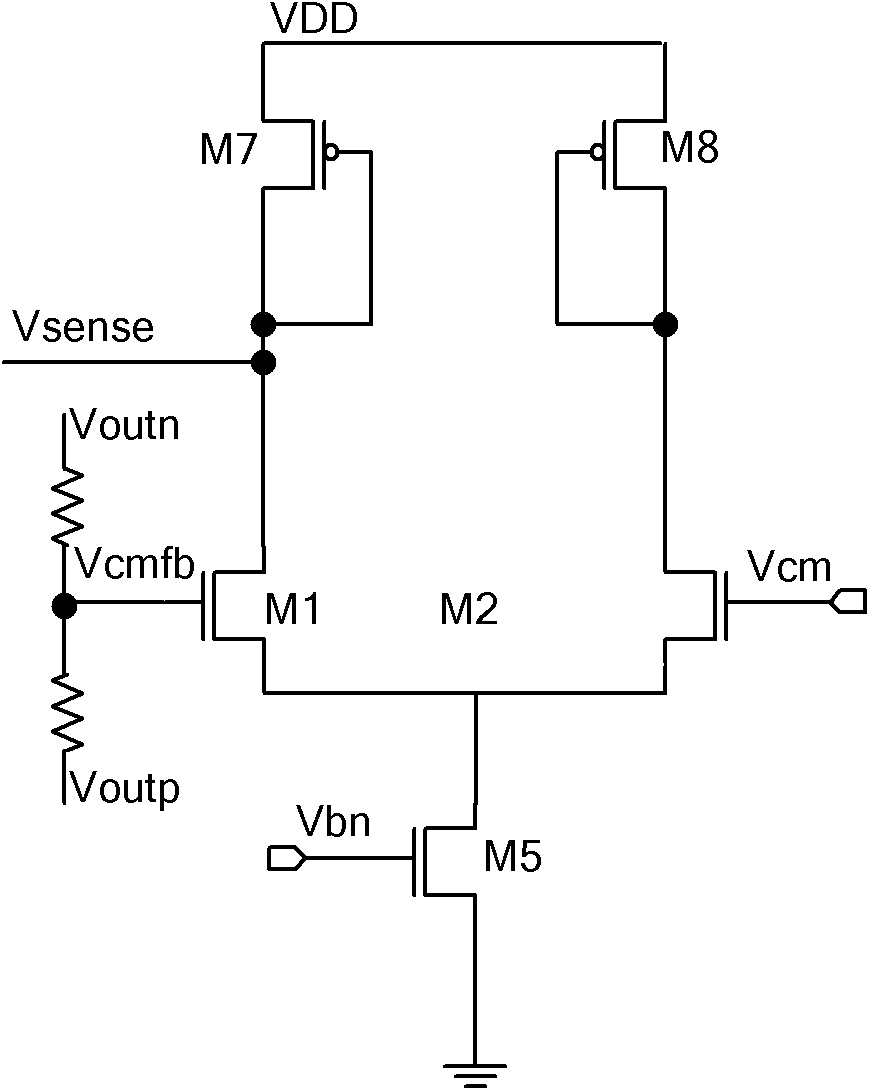
[0027] The design method and circuit of the large-bandwidth continuous-time common-mode feedback circuit of the present invention will be described in detail below in conjunction with the embodiments and the accompanying drawings.

[0028] The design method of the large-bandwidth continuous-time common-mode feedback circuit of the present invention includes the following steps:

[0029] 1) Design an ideal common mode signal (Vcm);

[0030] 2) Detect the common mode value (Vcmfb) of the output signal of the operational amplifier through the common mode detection circuit;

[0031] 3) Compare the detected common-mode value (Vcmfb) of the output signal of the operational amplifier with the ideal common-mode signal (Vcm);

[0032] 4) After the error signal (Vcmfb-Vcm) is amplified by the common-mode feedback circuit, two common-mode feedback control signals (Vsense1, Vsense2) are output and fed back to the drain of the bias tube of the operational amplifier bias circuit, so that t...


PUM


Abstract

The invention relates to a large-bandwidth continuous-time common-mode feedback circuit and a design method thereof. The method comprises the following steps of: designing an ideal common-mode signal; detecting the common-mode value of an operational amplification output signal through a common-mode detection circuit; comparing the detected common-mode value of the operational amplification output signal with that of the ideal common-mode signal; after amplifying an error signal through the common-mode feedback circuit, outputting two common-mode feedback control signals fed back to the drain electrode of a biasing tube of an operational amplification biasing circuit so that the whole common-mode feedback circuit forms a single-stage amplifier to ensure that the common-mode feedback circuit has enough phase margin; and finally stabilizing the operational-amplified output common-mode point on the ideal common-mode value according to the negative feedback function of common-mode feedback. The invention overcomes the defects that the traditional continuous-time common-mode feedback circuit is a multi-stage amplifier and has poor stability, and ensures that the common-mode feedback circuit is a one-stage common-source cathode-input amplifier through adjusting the feedback point of the common-mode feedback; and the common-mode feedback circuit has favorable stability and is suitable for large-bandwidth ultrahigh-speed full-differential analog circuits.

Description

technical field [0001] The invention relates to a common mode feedback circuit. In particular, it relates to a design method and circuit of a large-bandwidth continuous-time common-mode feedback circuit with first to tenth bias tubes, which is applied to a fully differential operational amplifier to meet the high bandwidth and stability requirements of the operational amplifier. Background technique [0002] The fully differential circuit has become a common circuit form due to its high output swing and the suppression of common-mode noise such as power supplies. The key and difficult point of the fully differential circuit design is the design of the common-mode feedback circuit, and the common-mode feedback circuit is a fully differential operational amplifier. In high-gain amplifiers, the output common-mode level is quite sensitive to device characteristics and mismatches, and cannot be stabilized by differential feedback. Therefore, a common-mode feedback network must b...

Claims


Application Information

Patent Timeline
IPC IPC(8): H03F3/45H03F1/34
Inventor 高静涂明强
Owner TIANJIN UNIV
Why Eureka
Try Eureka